Conserving components of fluids

Inactive Publication Date: 2007-04-10
TOTAL SEPARATION SOLUTIONS
View PDF28 Cites 66 Cited by
  • Summary
  • Abstract
  • Description
  • Claims
  • Application Information

AI Technical Summary

Benefits of technology

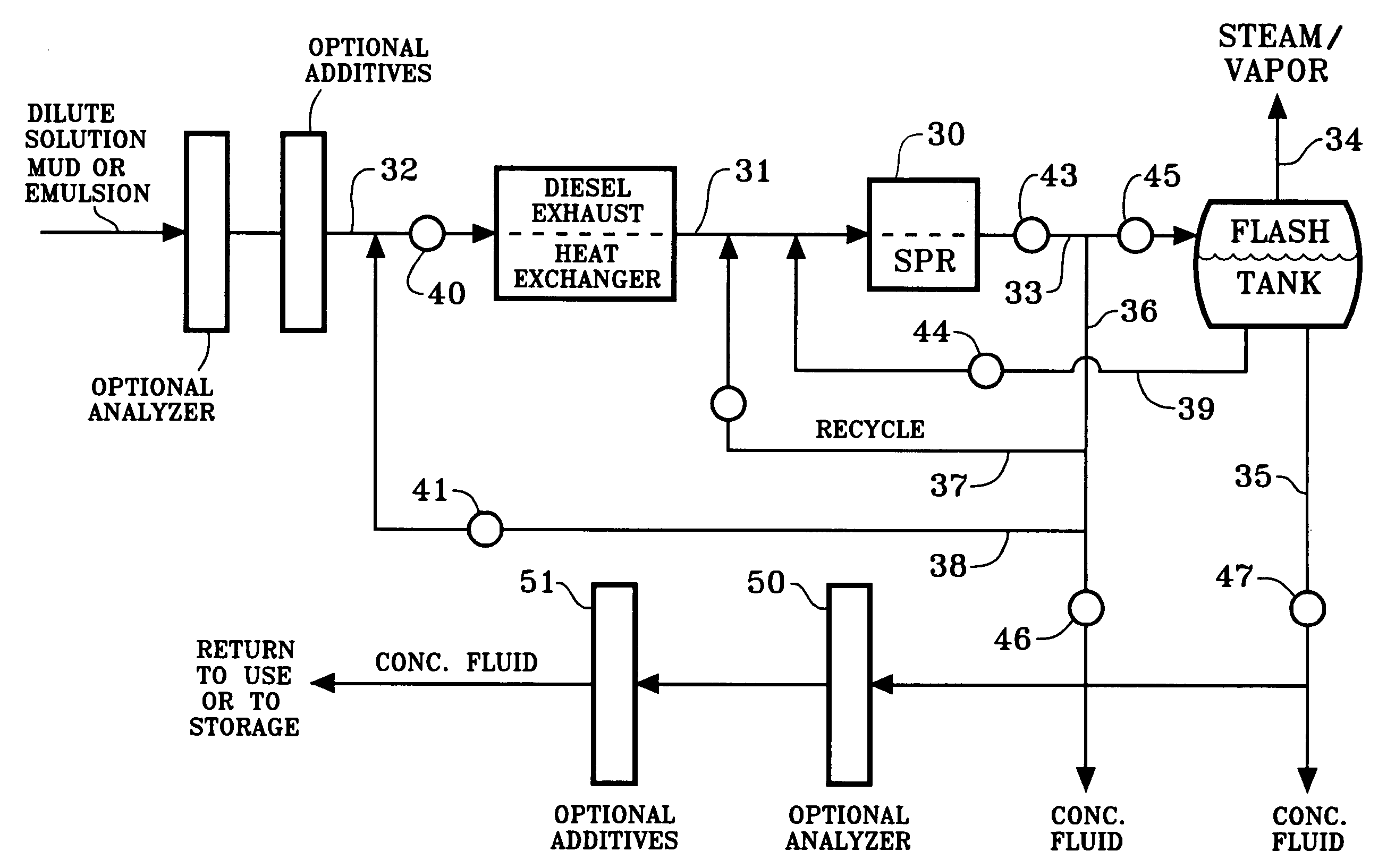
[0013]Our invention includes the optional step of filtering the fluid prepared by the SPR. Typically, in the prior art, the dilute, contaminated, or used oil well fluids are filtered before they are stored or processed by distillation. Our invention postpones filtration until after the used fluid is concentrated by passing through the SPR; filters and the filtration process can be engineered more efficiently to handle smaller volumes of liquid with higher concentrations of solids. Thus our invention includes a process of preparing a recycled oil well fluid comprising passing the fluid through a cavitation device and then filtering the concentrated fluid thus obtained. Persons skilled in the art will readily see that filtering significant quantities of solids after water removal rather than before contrasts dramatically with a distillation process.

Problems solved by technology

A conventional distillation process would tend to scale out some of the constituents in more or less difficultly predictable portions and relationships.

Method used


Image

  • Conserving components of fluids
  • Conserving components of fluids
  • Conserving components of fluids

Examples


example

Oil Mud Emulsion

[0036]Using a 15″ by 2″ cavitation device, ten gallons of oil mud emulsion were treated to remove water. Initially the oil mud emulsion contained 18% water by volume, the balance being oil and solids typical of an oil well mud. The oil mud emulsion was sent through the cavitation device operating at 3600 RPM and recycled through the tank, which rapidly increased the temperature of the oil mud emulsion from room temperature to 240° F. Once that temperature was reached, the RPM of the cavitation device was controlled automatically in order to maintain an outlet temperature 240° F. At equilibrium, while recirculating the material and continuing to recycle through the tank, the speed was maintained at 1700 RPM, requiring about 13.5 HP. At 15 minutes, the material contained 13% water; at 30 minutes, it contained 10% water, and at 45 minutes the water was reduced to 5% by volume. Essentially none of the oil was evaporated

[0037]As indicated above in the Summary of the Inven...


PUM

PropertyMeasurementUnit
boiling pointaaaaaaaaaa
angleaaaaaaaaaa
temperatureaaaaaaaaaa

Abstract

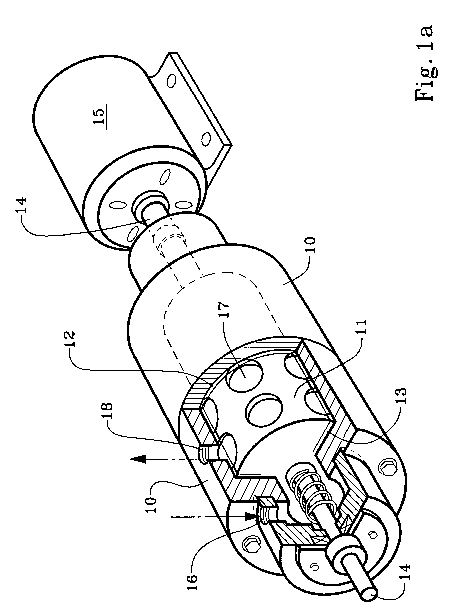
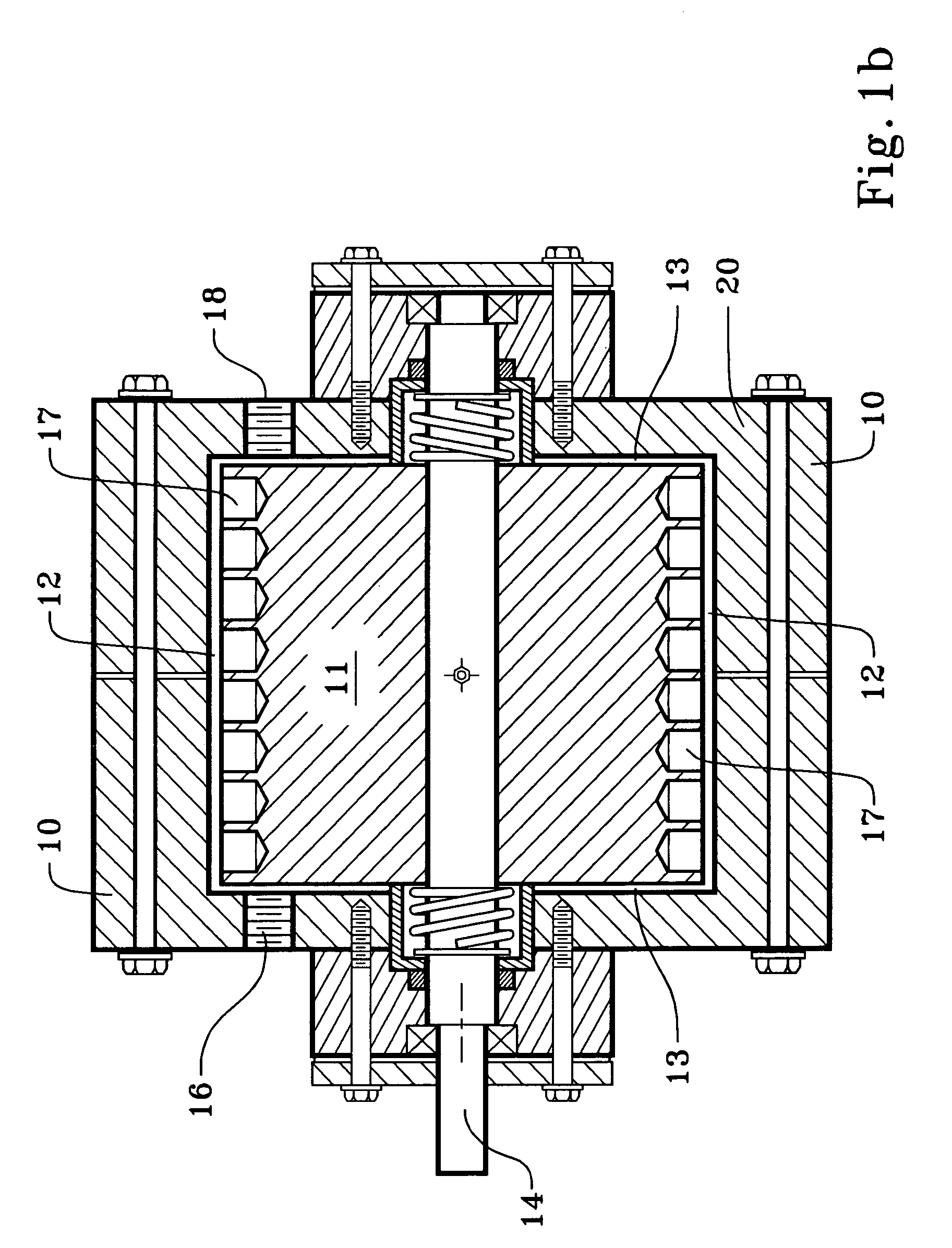
A cavitation device is used to heat, concentrate and recycle or otherwise reuse dilute and other oil well fluids, brines and muds, and solution mining fluids, all of which commonly contain ingredients worthy of conservation. The cavitation device is powered by a Diesel engine whose exhaust may be used to heat the incoming fluid, and the product of the cavitation device is directed to a flash tank.

Description

RELATED APPLICATION[0001]This application claims the full benefit of provisional application 60 / 652,549 filed Feb. 14, 2005 and 60 / 652,711 filed Feb. 14, 2005.TECHNICAL FIELD[0002]A cavitation device is used to concentrate and recycle or otherwise reuse oil well fluids and muds, solution mining fluids, and industrial oil / water emulsions, all of which commonly contain ingredients worthy of conservation.BACKGROUND OF THE INVENTION[0003]In oil and other hydrocarbon production, completion and workover fluids are typically circulated down the string of tubes and upwards around the outside of the tubes, contacting the formation surface of the wellbore from which the hydrocarbons are to be produced. An original clear brine is typically prescribed to have a density which is a function of the formation pressure, The salts and other additives in the completion or workover fluid may be partially diluted by the formation water, as a result of contact with the formation. The brines can also beco...

Claims


Application Information

Patent Timeline
Patent Type & Authority Patents(United States)
IPC IPC(8): E21B43/40E21B21/06B01D17/02B01D17/04
CPCB01D17/044E21B21/063B01D17/047B01D17/02B01D17/0205B01D17/04E21B43/40
Inventor SMITH, KEVIN W.SLOAN, ROBERT L.
Owner TOTAL SEPARATION SOLUTIONS
Why Eureka
Try Eureka