Multi-display apparatus and method thereof

Inactive Publication Date: 2008-09-18
SAMSUNG ELECTRONICS CO LTD
View PDF12 Cites 41 Cited by
  • Summary
  • Abstract
  • Description
  • Claims
  • Application Information

AI Technical Summary

Benefits of technology

[0010]The present invention provides a multi-display apparatus that can simultaneously mitigate a disconnection of an image and its perspective difference in terms of becoming disconnected at a seam between panels.

Problems solved by technology

Therefore, there is a limitation in improving the disconnection of an image at the seam between the pair of unit panels 10 in the above-described parallel connection structure.

Method used


Image

  • Multi-display apparatus and method thereof
  • Multi-display apparatus and method thereof
  • Multi-display apparatus and method thereof

Examples


Embodiment Construction

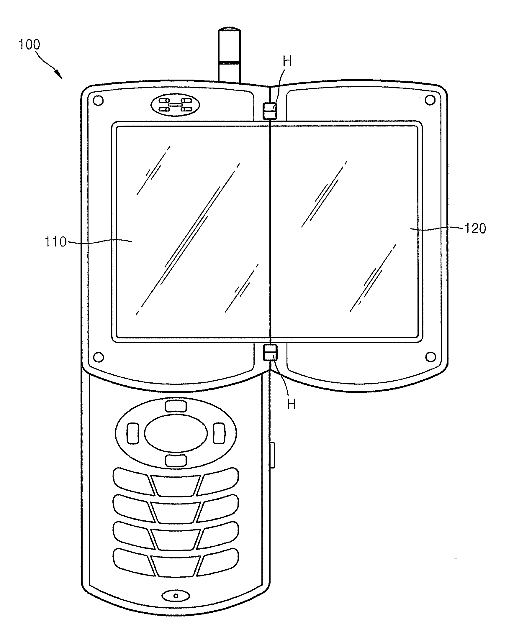
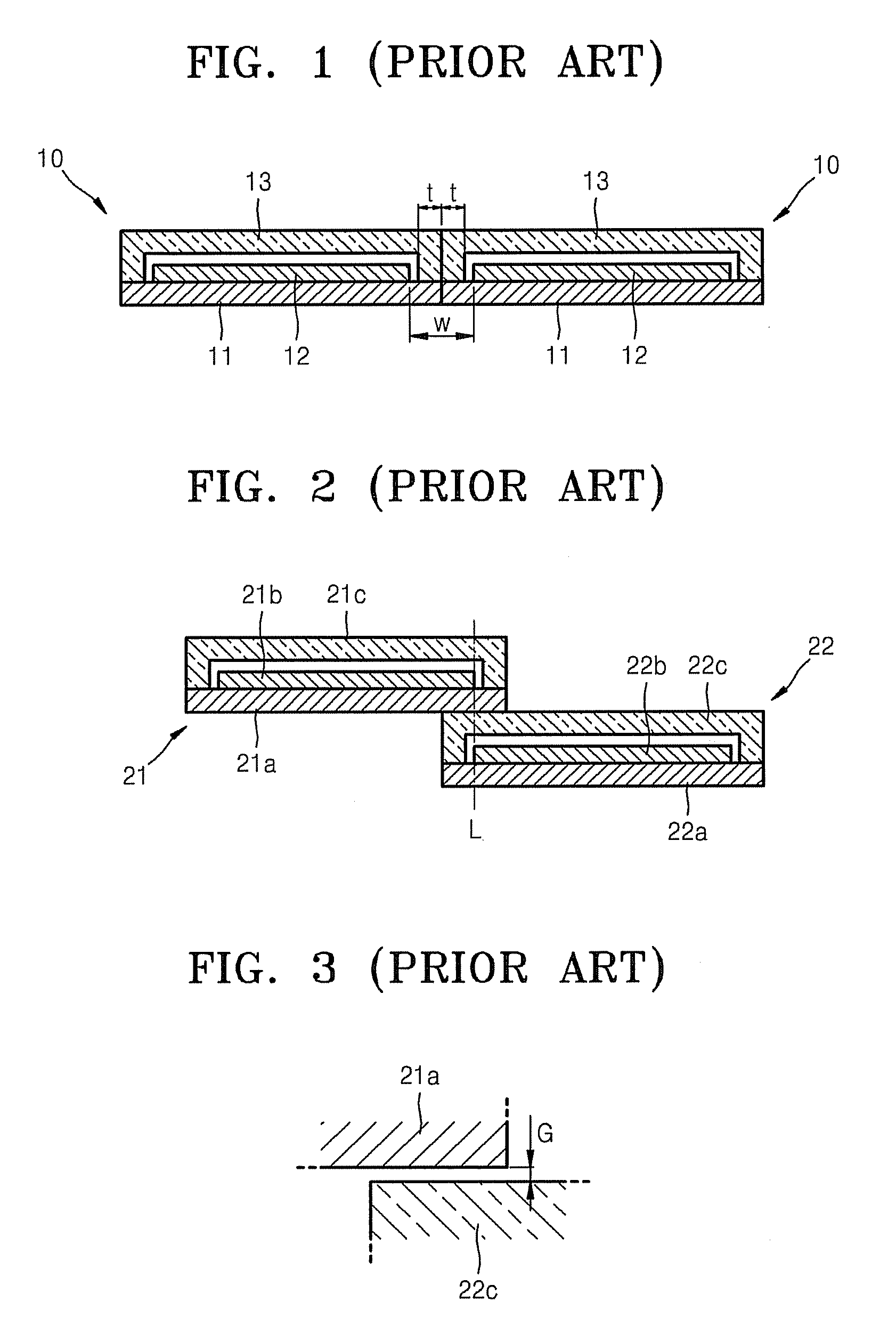
[0023]With reference again to FIG. 2, it is noted that there is a perspective difference in a connected image due to a large height difference between the first and second unit panels 21 and 22. That is, since the distances for the light respectively emitted from the unit panels 21 b and 22b to reach the eyes of a user are different as much as the height difference between the first and second unit panels 21 and 22, as the height difference between the first and second unit panels 21 and 22 increases, the image cannot be viewed smoothly due to the perspective difference in the connected image. Additionally, it is noted that an air gap G between the pair of panels as depicted in FIG. 3 occurs even when a structural tolerance between the pair of panels is well matched when the stack layer type structure as depicted in FIG. 2 is manufactured. Accordingly, the perspective view of the image is further affected at the seam.

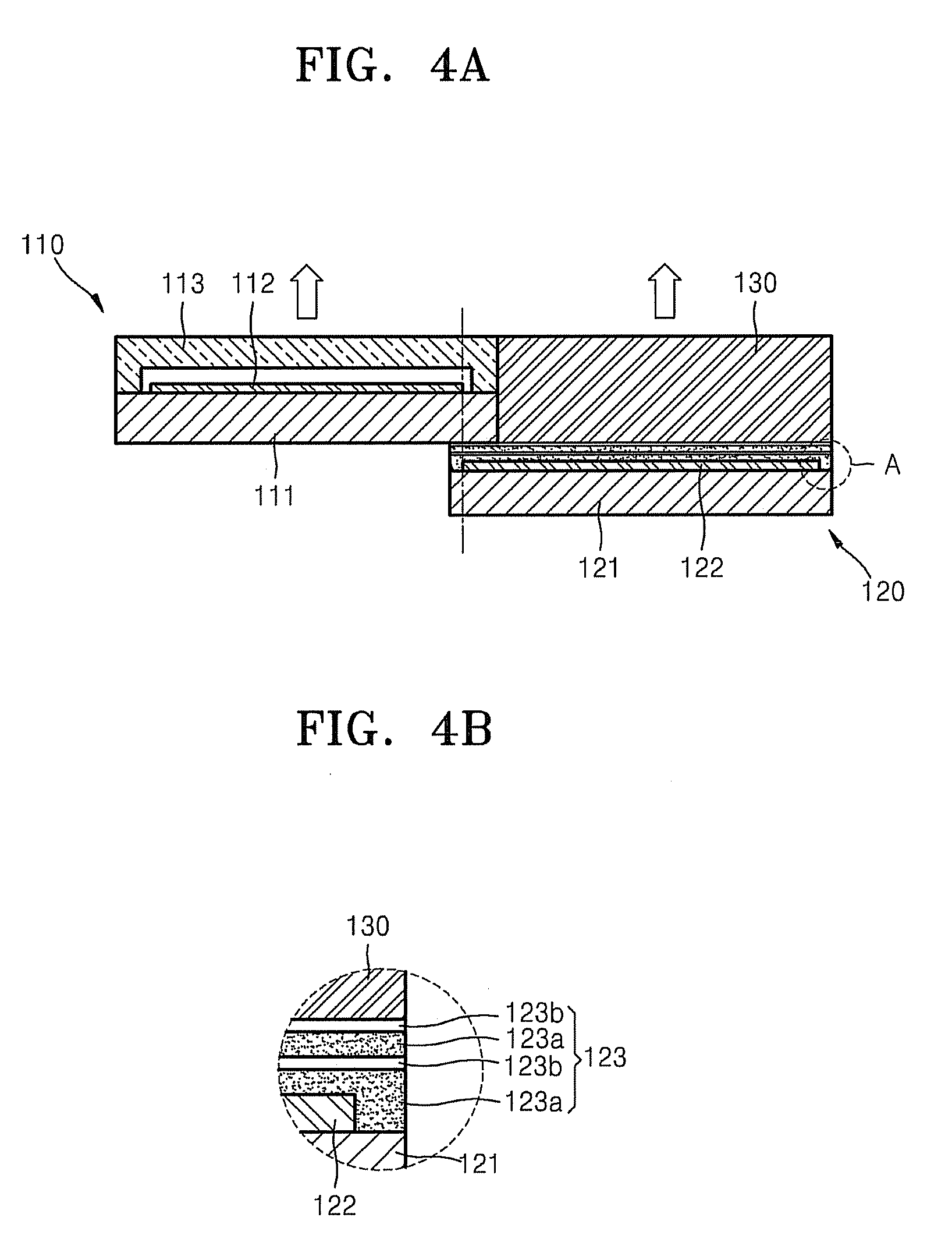
[0024]As will be described below, a multi-display apparatus that c...


PUM


Abstract

A multi-display apparatus includes two panels disposed with a step difference so that pixel boundaries of display devices formed on substrates overlap, and at least one of the two panels includes a thin film encapsulation layer covering the display device and disposed on an adjacent surface of one of the two panels where there is the step difference to improve a disconnection of an image at a seam between the two panels, and mitigate a perspective difference of the image at the seam due to the step difference between the two panels, thereby realizing a large natural and smooth image.

Description

[0001]This application claims priority to Korean Patent Application No. 10-2007-0026249, filed on Mar. 16, 2007, and all the benefits accruing therefrom under 35 U.S.C. §119, the contents of which in its entirety are herein incorporated by reference.BACKGROUND OF THE INVENTION[0002]1. Field of the Invention[0003]The present invention relates to a multi-display apparatus that realizes an image by connecting a plurality of panels, and a method thereof, and more particularly, to a multi-display apparatus that can minimize a disconnection of an image at seams of the multi-display apparatus, and a method thereof.[0004]2. Description of the Related Art[0005]Multi-display apparatuses realize a large screen by connecting a plurality of display panels. In the past, a large screen was realized by connecting a plurality of Braun tubes, also known as cathode ray tubes (“CRTs”), into a large TV. However, recently, due to an increasing demand for a large screen in small mobile apparatuses such as...

Claims


Application Information

Patent Timeline
IPC IPC(8): G09G5/00G09F9/00G09F9/40
CPCG09G3/20H01L27/3293G09G2300/0426G09G2300/026H10K59/18G06F1/1613G06F1/1616G06F1/1622G06F1/1637G06F1/1641G06F2200/161
Inventor LEE, YOUNG-GUKEE, IN-SEOKO, ICK-HWANSHIM, HONG-SHIK
Owner SAMSUNG ELECTRONICS CO LTD
Why Eureka
Try Eureka