Methods for setting the contact pressure of a displaceably mounted roller

a technology of displaceable rollers and contact pressures, which is applied in the direction of printing presses, rotary presses, printing presses, etc., can solve the problems of large technical apparatus expenditure, inability to adjust the contact pressure of all adjustable rollers at the same time, and the number of valves means a large amount of technical apparatus

Inactive Publication Date: 2008-09-25
SCHNEIDER GEORG +2
View PDF16 Cites 42 Cited by
  • Summary
  • Abstract
  • Description
  • Claims
  • Application Information

AI Technical Summary

Benefits of technology

[0017]This type of control of the pressure is important particularly in connection with forme cylinders on whose circumference fastening assemblies, for use in fastening the printing plates on the forme cylinder, are provided. If the adjustment or the bringing into contact of the adjustable rollers is performed at an angular position in which the adjustable roller comes to rest on the fastening device of the forme cylinder, the adjusted values are distorted because of the changed diameter of the forme cylinder in the area of the fastening device. This distortion can be avoided by controlling the angular position of the second roller.

Problems solved by technology

Since a multitude of adjustable rollers are provided in a typical dampening unit or inking unit, normally a number of valves corresponding to the number of actuators would be required, which larger number of valves means a large outlay in technical apparatus.
This means that the adjustable rollers cannot all be adjusted at the same time.

Method used


Image

  • Methods for setting the contact pressure of a displaceably mounted roller
  • Methods for setting the contact pressure of a displaceably mounted roller
  • Methods for setting the contact pressure of a displaceably mounted roller

Examples


Embodiment Construction

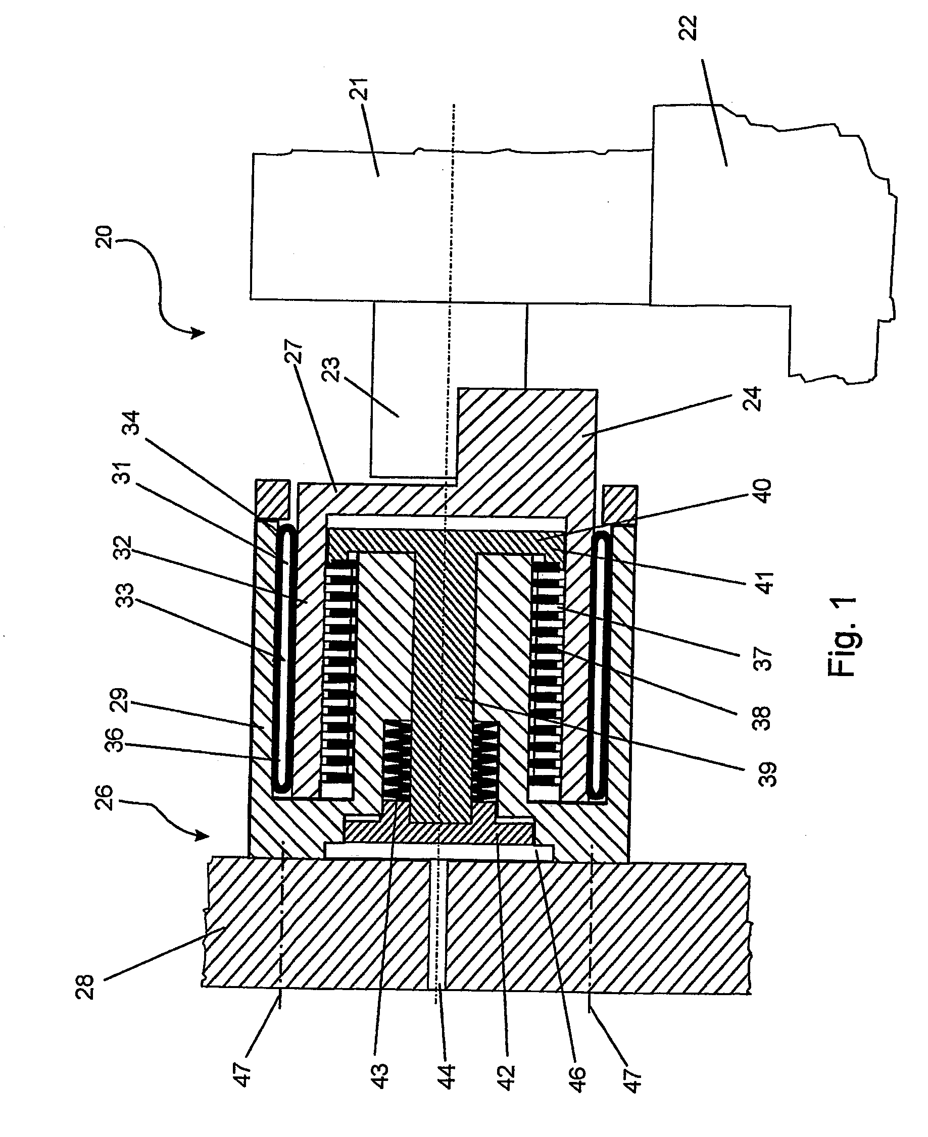
[0028]Referring initially primarily to FIG. 1, there may be seen a device generally at 20, for setting the contact pressure between a first roller 21 and a second roller 22 in accordance with the present invention. The first roller 21 can be releasably fastened, by the end of its shaft 23, or its journal, at a quick-release locking device 24 provided on the device 20. Such quick-release locking devices are generally known from the prior art and typically have a semi-circular bearing shell, into which semi-circular shell the ends of the shaft 23 can be placed. By fastening an upper bearing shell, which is not specifically represented in FIG. 1, the shaft 23 can be fixed in place in the quick-release locking device 24.

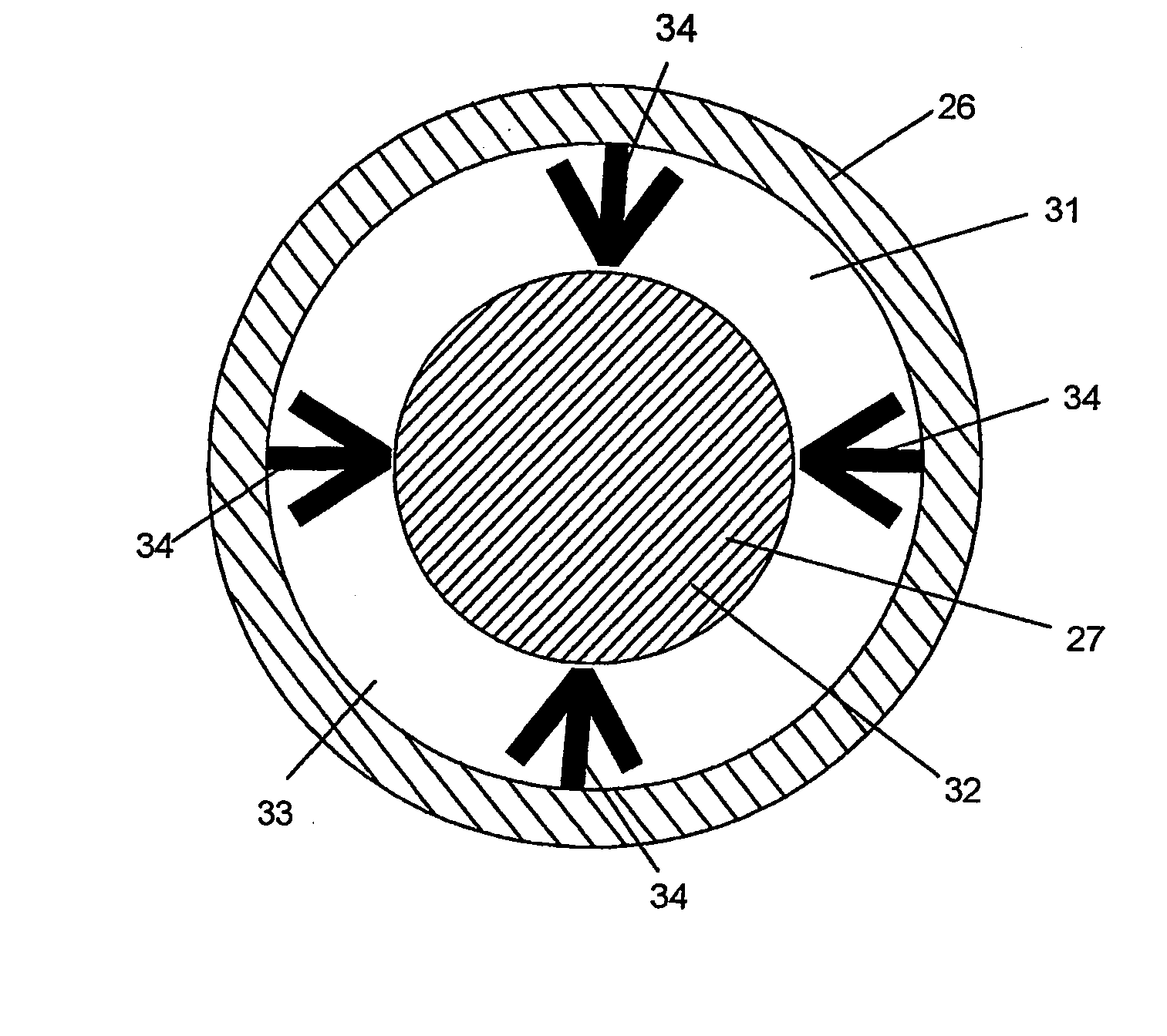
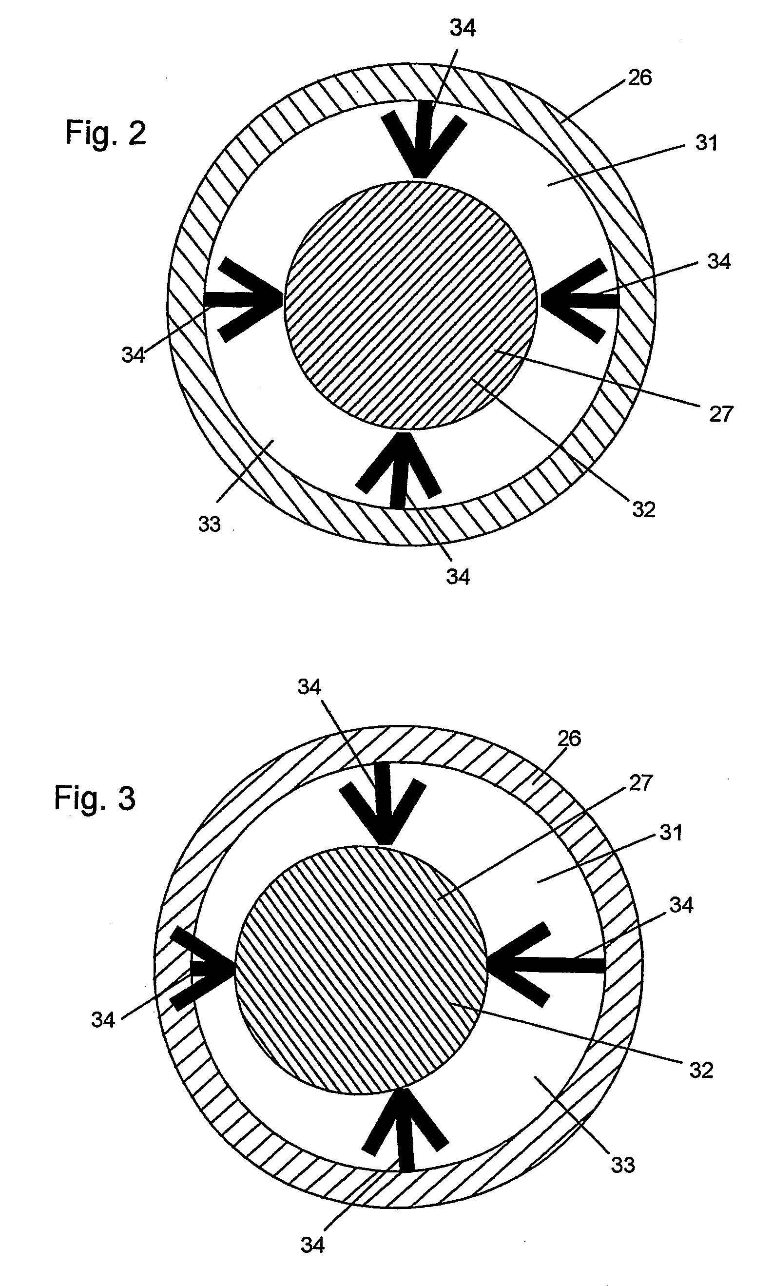
[0029]The contact pressure setting device 20 is substantially put together from a frame holder 26 and a roller holder 27, which frame and roller holders 26 and 27, respectively can be displaced, in relation to each other, in an actuating plane that is extending perpendic...


PUM


Abstract

A method is used to set a contact pressure between a displaceable roller and another roller or for moving the displaceable roller with respect to the other roller. At least one actuator is subjectible to the action of a pressure medium and presses the displaceable roller toward the other roller with an adjustable force. The pressure of the pressure medium can be adjusted by a valve. A switchover device is provided for use in connecting the valve to different actuators, as desired.

Description

CROSS-REFERENCE TO RELATED APPLICATIONS[0001]This U.S. patent application is a division of U.S. application Ser. No. 10 / 528,468, filed Mar. 21, 2005. That application is the U.S. national phase, under 35 U.S.C. 371, of PCT / DE2003 / 002946, filed Sep. 5, 2003; published as WO 2004 / 028810A1 on Apr. 8, 2004, and claiming priority to DE 102 44 046.8, filed Sep. 21, 2002, the disclosures of which are expressly incorporated herein by reference.FIELD OF THE INVENTION[0002]The present invention is directed to methods for setting the contact pressure of a displaceably seated roller. The contact pressure, or a spacing distance between the displaceable roller and a second roller is variable by the use of the actuator that can be charged with a pressure medium.BACKGROUND OF THE INVENTION[0003]A plurality of rollers are contained in generally conventional printing presses, such as web-fed rotary printing presses, for example. Inking rollers, in particular, are provided in such presses, which inkin...

Claims


Application Information

Patent Timeline
Patent Type & Authority Applications(United States)
IPC IPC(8): B41F1/34B41F13/34B41F31/30B41F31/32B41F31/36B41F33/10
CPCB41F7/40B41F13/34B41F31/36B41F31/301B41F13/40
Inventor SCHNEIDER, GEORGFAIST, BERND KLAUSJENTZSCH, PETER
Owner SCHNEIDER GEORG
Why Eureka
Try Eureka