Hydrodynamic torque converter

a technology of torque converter and hydraulic pump, which is applied in the direction of rotary clutch, fluid coupling, gearing, etc., can solve the problems of subsequent machining of outer and inner plate carriers, and carrying out any subsequent machining

Inactive Publication Date: 2002-03-21
ZF FRIEDRICHSHAFEN AG
View PDF0 Cites 53 Cited by
  • Summary
  • Abstract
  • Description
  • Claims
  • Application Information

AI Technical Summary

Problems solved by technology

A problem arising in torque converters of the type mentioned above is that the welding process for connecting the outer and inner plate carriers requires carrying out subsequent machining procedures, e.g., reworking in the area of the weld.
Another problem is that the design of the torque converter must allow fluid to pass through the lockup clutch even when a torque transmission connection is produced via the lockup clutch.
Accordingly, openings must be introduced in the outer circumferential area of the outer plate carrier in this known torque converter which constitutes an additional work step which is difficult to carry out.
Therefore, it is unnecessary in practice to carry out any subsequent machining processes after the various components have been connected by laser welding.

Method used


Image

  • Hydrodynamic torque converter
  • Hydrodynamic torque converter
  • Hydrodynamic torque converter

Examples


Embodiment Construction

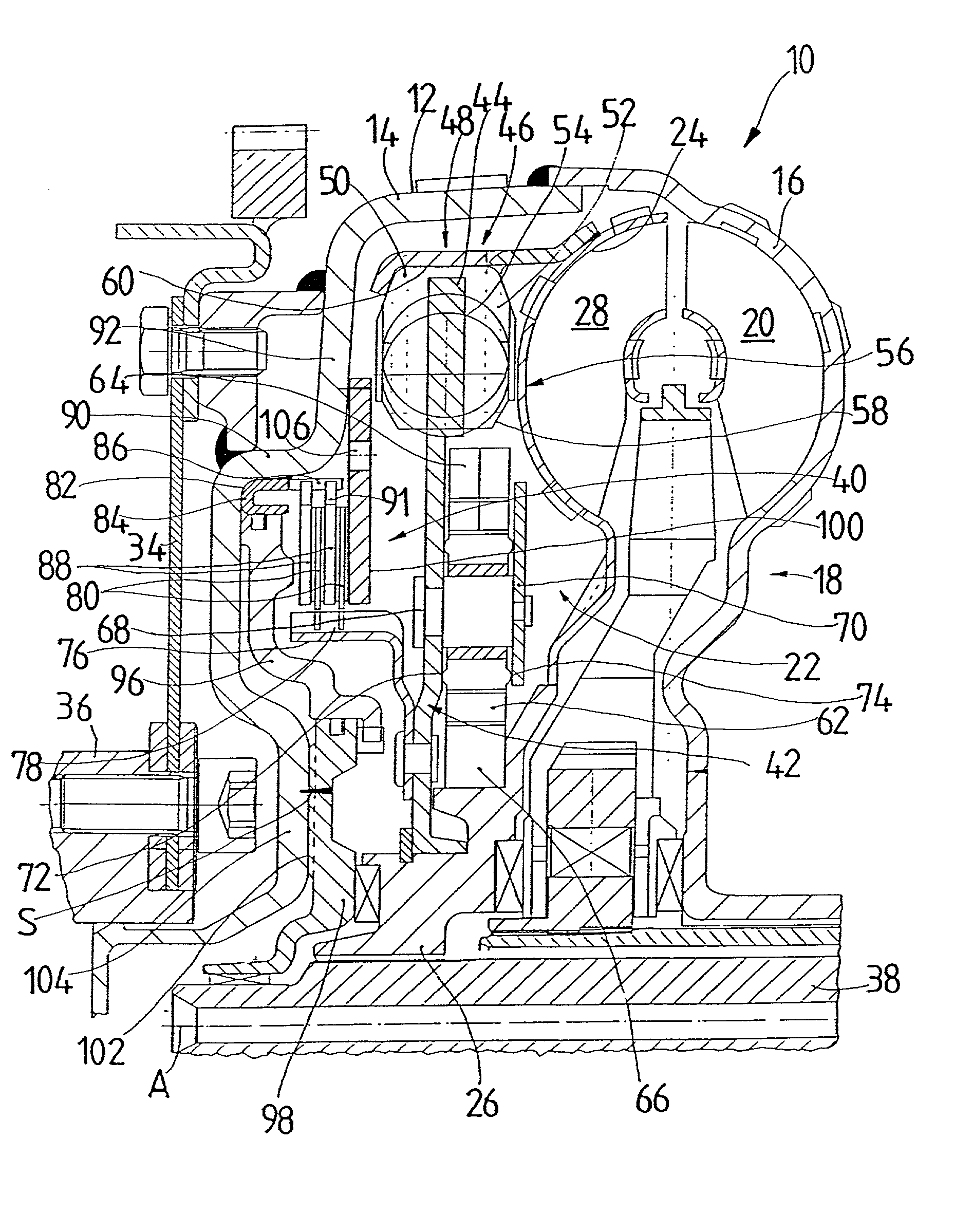
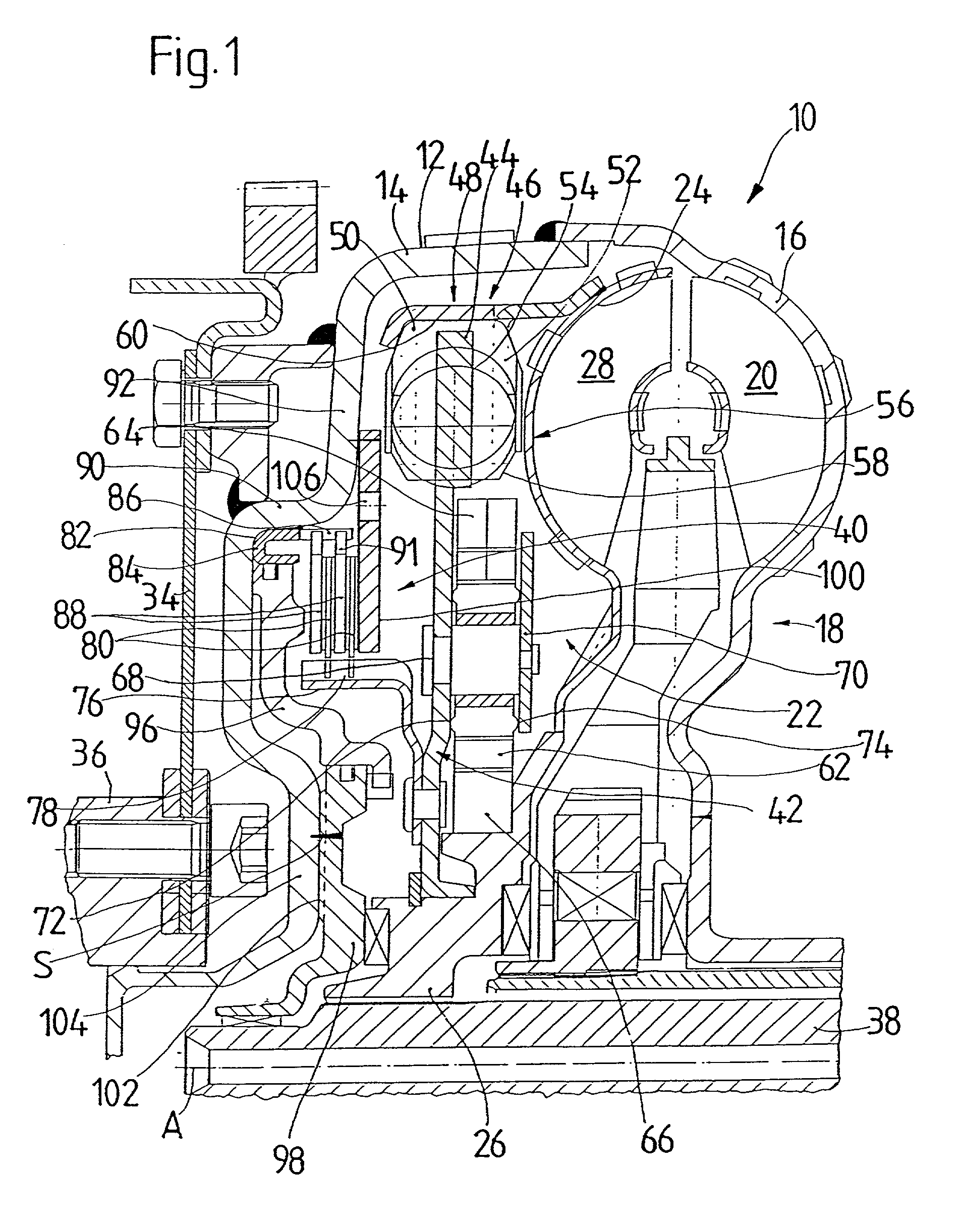
[0046] FIG. 1 shows a partial longitudinal section a hydrodynamic torque converter 10 according to an embodiment of the present invention. The construction of the torque converter is known in principle and will be described briefly in the following. The torque converter 10 has a housing 12 including a housing cover 14 and an impeller wheel shell 16 of an impeller wheel 18. The connection of the impeller wheel shell 16 to the housing cover 14 is made by welding. The impeller wheel shell 16 carries a plurality of impeller wheel blades 20 along an inner side. A turbine wheel 22 is arranged in the interior of the torque converter 10 and includes a turbine wheel shell 24 and a turbine wheel hub 26. A plurality of turbine wheel blades 28 are positioned in a successive manner in the circumferential direction in the turbine wheel shell 24. A stator wheel 30 having a plurality of stator wheel blades 32 is located between turbine wheel 22 and the impeller wheel 18.

[0047] The converter housing...


PUM


Abstract

A hydrodynamic torque converter includes a converter housing and a turbine wheel which is arranged in the converter housing and is rotatable with respect to the converter housing about a rotational axis of the converter. The torque converter further includes a lockup clutch for producing a torque transmission connection between the converter housing and the turbine wheel. The lockup clutch has a first friction surface arrangement held by a first friction surface carrier arrangement substantially fixed with respect to rotation relative to the converter housing, a second friction surface arrangement is held by a second friction surface carrier arrangement substantially fixed with respect to rotation relative to the turbine wheel, a contact pressing arrangement for pressing the first and the second friction surface arrangement against one another in frictional contact, and an abutment arrangement at which the first and second friction surface arrangement can be supported substantially in the direction of the axis of rotation when pressed by the contact pressure arrangement. The first friction surface carrier arrangement has a substantially annular body region connected either directly or indirectly with the converter housing and driver projections which are arranged at a distance from one another in the circumferential direction proceeding from the body region. Respective counter-driver projections at the first friction surface arrangement engage between these driver projections.

Description

[0001] 1. Field of the Invention[0002] The present invention is directed to a hydrodynamic torque converter with a converter housing, a turbine wheel arranged in the converter housing that is rotatable with respect to the converter housing about a rotational axis, and a lockup clutch via which a torque transmission connection is producible between the converter housing and the turbine wheel, wherein the lockup clutch has a first friction surface arrangement which is held by a first friction surface carrier arrangement with respect to the converter housing so as to be substantially fixed with respect to rotation relative to it, a second friction surface arrangement which is held by a second friction surface carrier arrangement with respect to the turbine wheel so as to be substantially fixed with respect to rotation relative to it, a contact pressing arrangement operative for pressing the first and the second friction surface arrangement against one another in frictional contact, and...

Claims


Application Information

Patent Timeline
Patent Type & Authority Applications(United States)
IPC IPC(8): F16H45/02
CPCF16H45/02F16H2045/021F16H2045/0268F16H2045/0284
Inventor SASSE, CHRISTOPHKUNDERMANN, WOLFGANGWIENHOLT, HANS-WILHELMGUDE, WOLFGANGBECHMANN, DIETRICHWACK, ERWIN
Owner ZF FRIEDRICHSHAFEN AG
Why Eureka
Try Eureka