Tire tread having improved contact pressure distribution

a technology of contact pressure distribution and tire tread, which is applied in the direction of tyre tread bands/patterns, non-skid devices, tyre parts, etc., can solve the problems of reducing the efficiency of the tread, negatively affecting tire performance and durability, etc., and achieves the effect of improving traction

Inactive Publication Date: 2011-04-07
BOTT ANDREAS +3
View PDF10 Cites 56 Cited by
  • Summary
  • Abstract
  • Description
  • Claims
  • Application Information

AI Technical Summary

Benefits of technology

[0021]“Sipe” means small slots molded into the tread elements of the tire that subdivide the tread surface and improve traction, sipes are generally narrow in width and close in the tires footprint as opposed to grooves that remain open in the tire's footprint.

Problems solved by technology

Such concentrations of pressure can reduce the efficiency of the tread and negatively affect tire performance and durability.

Method used


Image

  • Tire tread having improved contact pressure distribution
  • Tire tread having improved contact pressure distribution
  • Tire tread having improved contact pressure distribution

Examples


Embodiment Construction

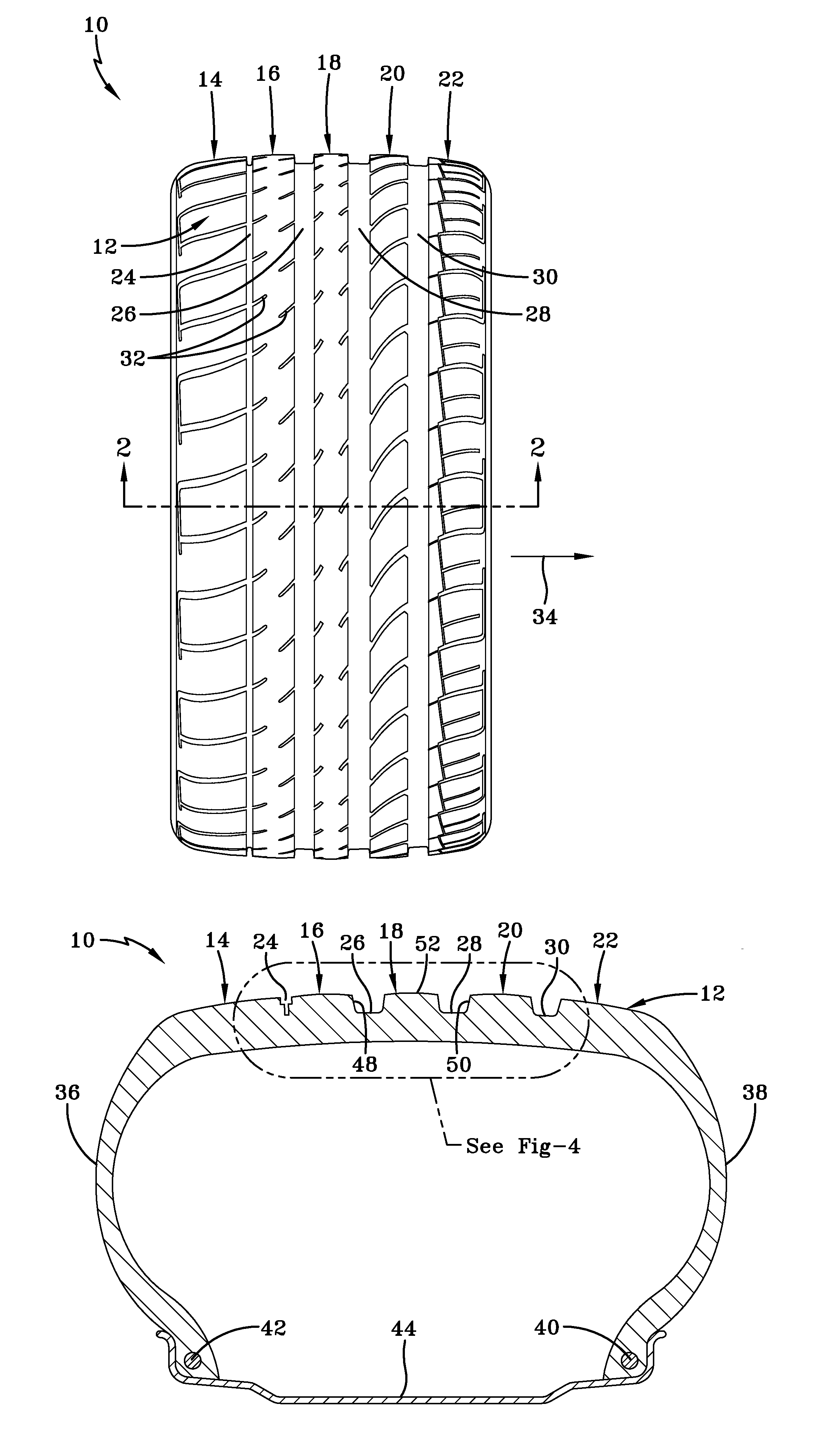
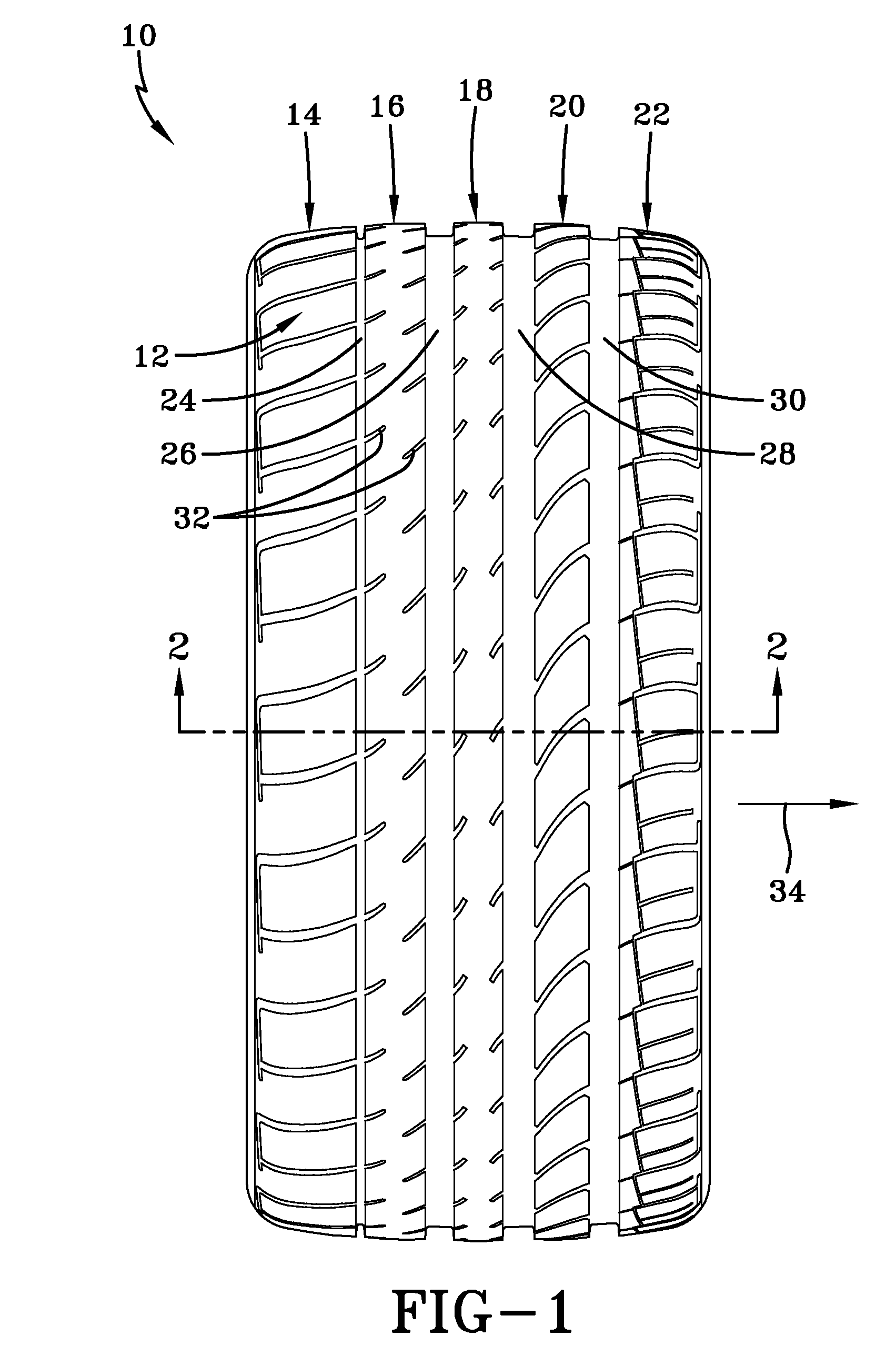
[0037]Referring to FIG. 1, a tire 10 is shown having a representative tread pattern 12 formed by circumferential ribs 14, 16, 18, 20, 22. The ribs are spaced apart by circumferential grooves 24, 26, 28, and 30. More or fewer ribs may constitute the pattern 12 is desired. The rib 18 lies on the equatorial centerplane of the tire 10. Each rib is uniquely constructed of respective tread elements; intermediary ribs 18, and 20 being of generally solid rib configuration with offset groove fingers 32 into the ribs from opposite rib edges. Ribs 14, 16, and 22 are shown as constructed from an array of discrete rib elements separated within the rib by lateral grooves. The tread pattern 12 extends between edges of the tire in a axial direction indicated in FIG. 1 by the numeral 34.

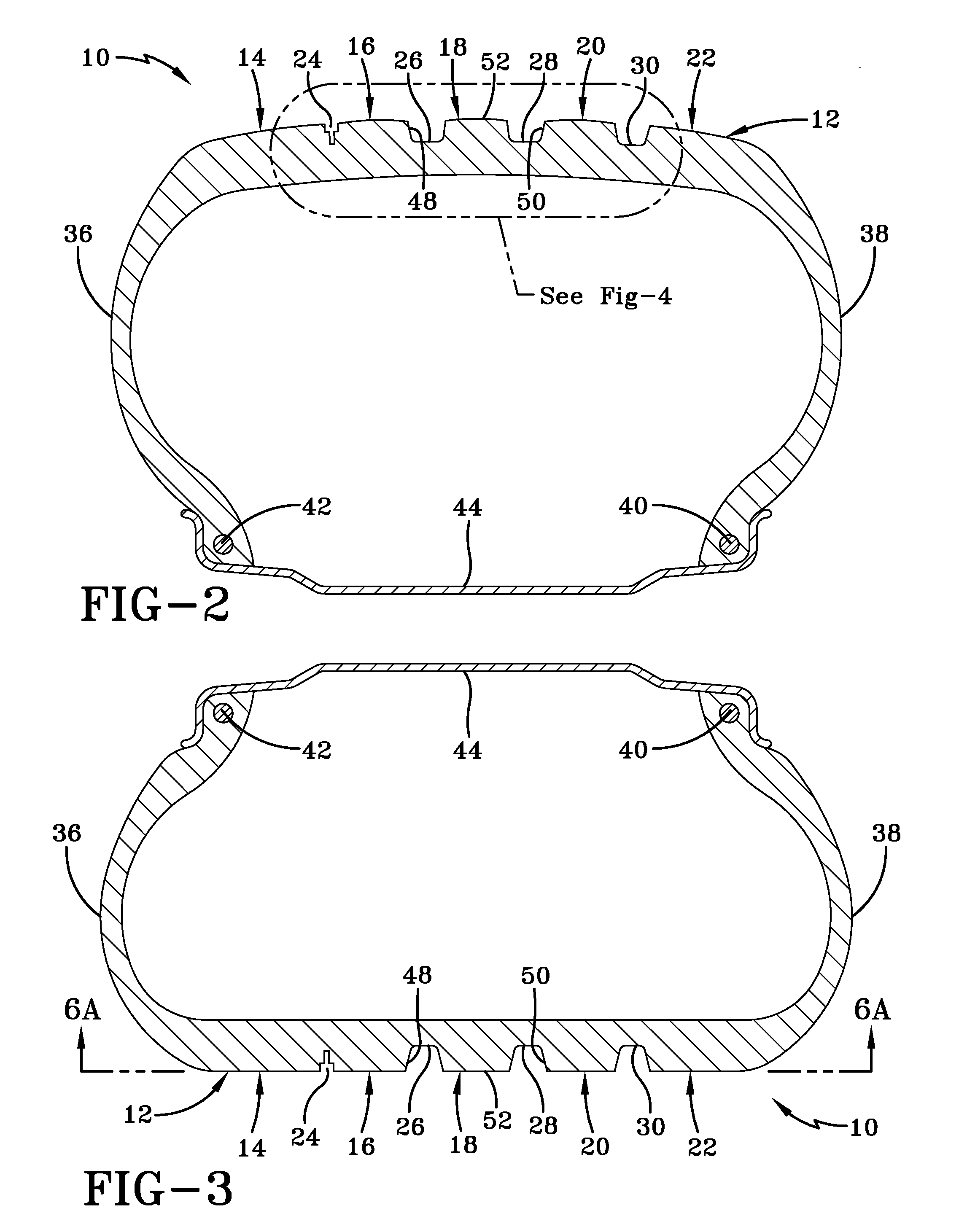
[0038]FIG. 2 shows the tread pattern 12 in section. The tire 10 is of conventional construction including a tread or crown region 12, sidewalls 36, 38 and a lower bead portion 40, 42. The tire 10 seats within a rim 4...


PUM


Abstract

A multi-rib tire tread has a plurality of circumferential spaced apart ribs in an axial direction, adjacent ribs separated by a circumferential grooves and each rib having sides extending radially outward to a radially outward contact surface. The outward contact surface of a central rib has an outwardly convex curvature in an axial direction more rounded than a tread curvature. A first lateral rib and a second lateral rib are positioned adjacent opposite sides of the central rib, each lateral rib having an outwardly convex curvature in an axial direction more rounded than a tread curvature. The convex curvature of the first and second lateral ribs are less rounded than the central rib. The radius of curvature of the center rib is within a range of 170 and 270 millimeters; the radius of curvature of the first lateral rib is within a range of 80 to 180 millimeters; and the radius of curvature of the second lateral rib is within a range of 100 to 200 millimeters.

Description

FIELD OF THE INVENTION[0001]The invention relates generally to a tire tread for general purpose passenger vehicle usage and, in particular to a tire tread having improved contact distribution capability across a contact footprint.BACKGROUND OF THE INVENTION[0002]Tire treads are designed to accomplish a number of objectives and meet numerous performance criteria and it is generally desirable to construct a tread providing good durability, traction, and handling performance on a range of surface conditions. Passenger tires are typically configured having multiple spaced apart and parallel circumferential ribs separated by circumferential grooves. The ribs are each formed by a circumferential array of block elements. The tire tread deflects during use to form a road surface contact footprint in which contact pressure is distributed across the rib pattern. Some tread patterns can develop a concentration of contact pressure in certain regions of the ribs within the tire footprint, partic...

Claims


Application Information

Patent Timeline
Patent Type & Authority Applications(United States)
IPC IPC(8): B60C11/04
CPCB60C11/0302B60C11/1392B60C11/0332B60C11/0306B60C11/1376
Inventor BOTT, ANDREASERCEG, BORISBRACHTL, MARKUSWADA, YASUO
Owner BOTT ANDREAS
Why Eureka
Try Eureka