Magnetic Latch Mechanism
a latch mechanism and magnet technology, applied in the field of magnet latch mechanism, can solve the problems of imperfect mechanical linkage between the doors and inability to close the doors at the same time,
- Summary
- Abstract
- Description
- Claims
- Application Information
AI Technical Summary
Benefits of technology
Problems solved by technology
Method used
Image

Examples
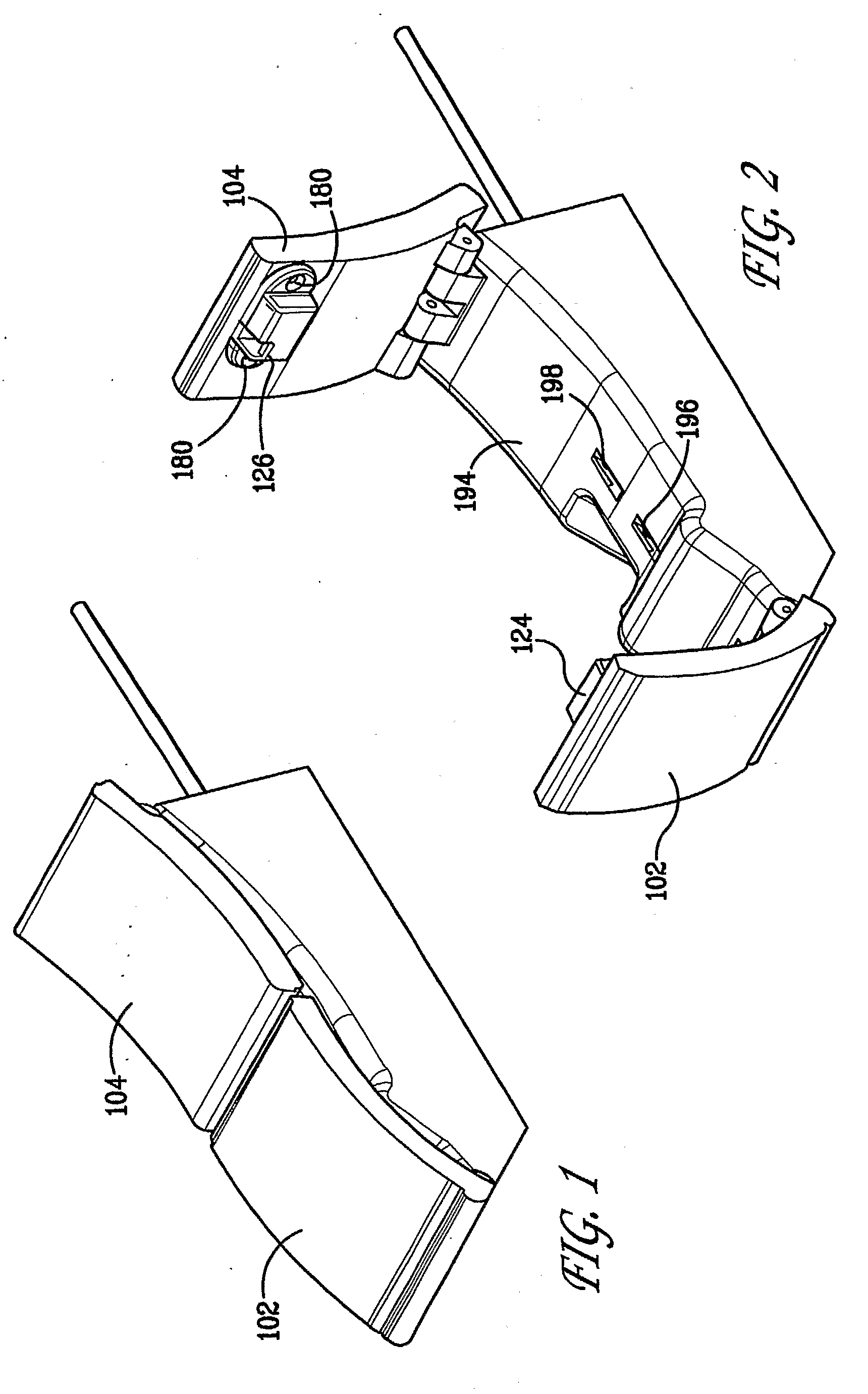
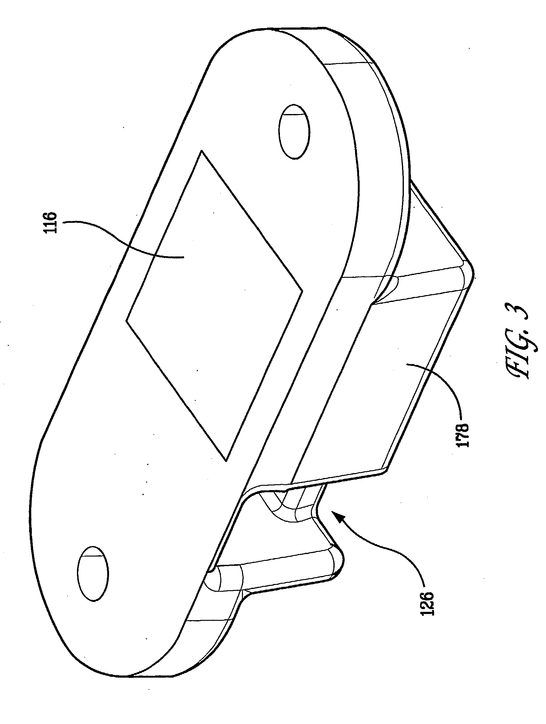
embodiment 100
[0035]Referring to FIGS. 1-71, an embodiment 100 of the magnetic latch mechanism with dual rotary magnets according to the present invention can be seen. The latch mechanism 100 is a remotely operated latch mechanism designed to secure two doors 102 and 104 in the closed position substantially simultaneously, using two rotating magnets 106 and 108. The latch mechanism 100 is designed to be installed between the pivots or hinges of the doors 102, 104 with the rotary magnets 106, 108 supported for rotation about parallel and spaced-apart axes of rotation. Also, the rotary magnets 106, 108 rotate in the same direction. Each of the rotary magnets 106 and 108 are supported by a separate magnet carrier 118, 119, respectively. Each magnet carrier 118, 119 is rotationally supported by the housing 132. Each of the rotary magnets 106, 108 are attached to the respective magnet carrier 118, 119 such that the rotary magnet and its respective magnet carrier rotate as one unit. Each of the rotary ...
embodiment 200
[0084]Referring to FIGS. 119-174, an embodiment 200 of the magnetic latch mechanism with dual rotary magnets according to the present invention can be seen. The latch mechanism 200 is a remotely operated latch mechanism designed to secure two doors 202 and 204 in the closed position substantially simultaneously, using two rotating magnets 206 and 208. The latch mechanism 200 is designed to be installed between the pivots or hinges of the doors 202, 204 with the rotary magnets 206, 208 supported for rotation about parallel and spaced-apart axes of rotation. Also, the rotary magnets 206, 208 rotate in the same direction. Each of the rotary magnets 206 and 208 are supported by a separate magnet carrier 218, 219, respectively. Each magnet carrier 218, 219 is rotationally supported by the housing 232. Each of the rotary magnets 206, 208 are attached to the respective magnet carrier 218, 219 such that the rotary magnet and its respective magnet carrier rotate as one unit. Each of the rota...
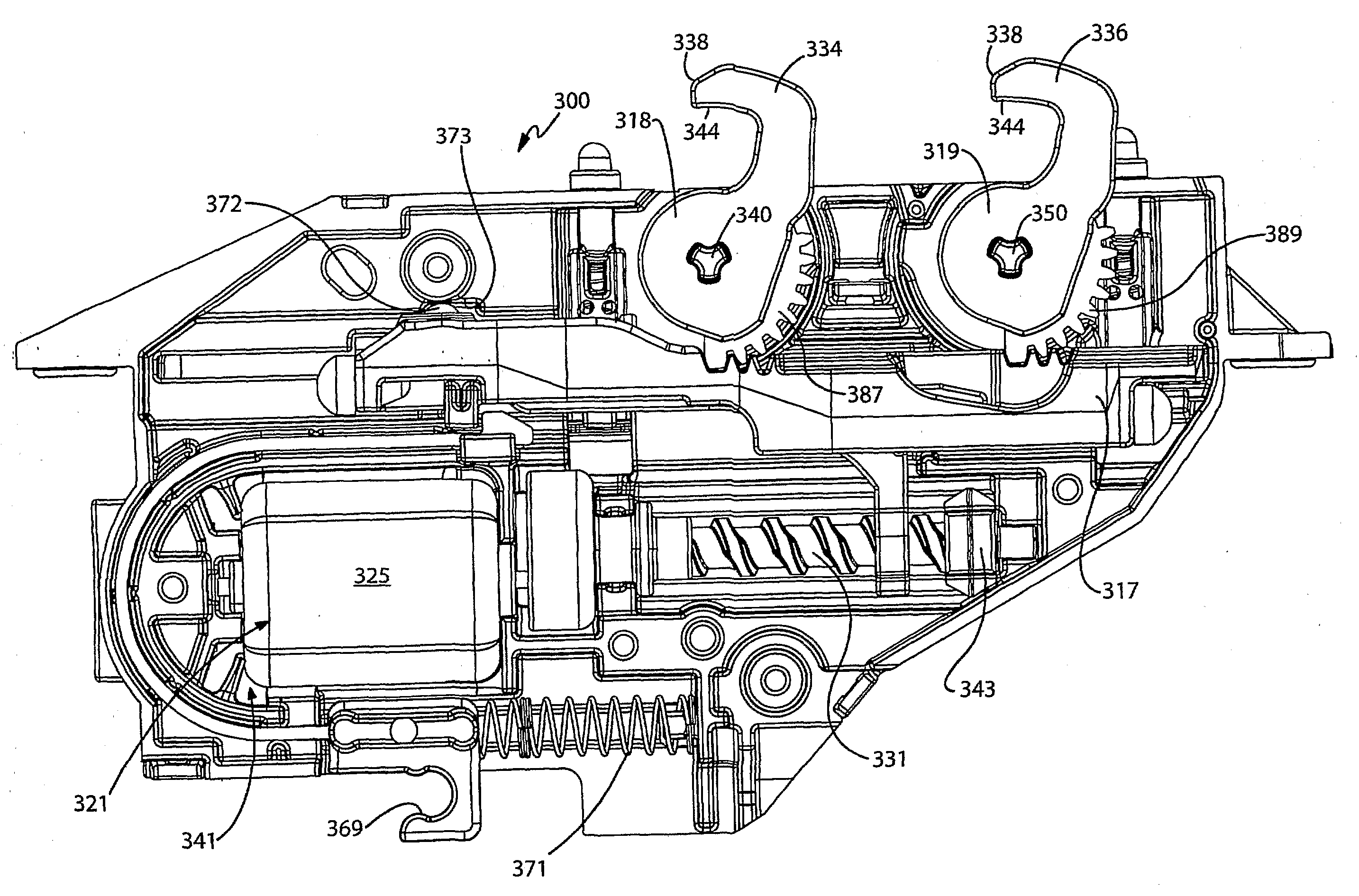
embodiment 300
[0120]Referring to FIGS. 175-297, an embodiment 300 of the magnetic latch mechanism with dual rotary magnets according to the present invention can be seen. The latch mechanism 300 is a remotely operated latch mechanism designed to secure two doors 302 and 304 in the closed position substantially simultaneously, using two rotating magnets 306 and 308. The latch mechanism 300 is designed to be installed between the pivots or hinges of the doors 302, 304 with the rotary magnets 306, 308 supported for rotation about parallel and spaced-apart axes of rotation. Also, the rotary magnets 306, 308 rotate in the same direction. Each of the rotary magnets 306 and 308 are supported by a separate magnet carrier 318, 319, respectively. Each magnet carrier 318, 319 is rotationally supported by the housing 332. Each of the rotary magnets 306, 308 are attached to the respective magnet carrier 318, 319 such that the rotary magnet and its respective magnet carrier rotate as one unit. Each of the rota...
PUM
 Abstract
Description
Claims
Application Information