
Anti-Shock Optical Recording and Reproducing Device

a reproducing device and optical recording technology, applied in the direction of recording information storage, instrumentation, disposition/mounting of heads, etc., can solve the problem of increasing the loop sensitivity to noise, not being fast enough to let the servo controller react, and not being able to detect properly a sudden rise in the radial error signal. , to achieve the effect of accurate and timely detection

Inactive Publication Date: 2008-09-25
KONINKLIJKE PHILIPS ELECTRONICS NV
View PDF2 Cites 4 Cited by
  • Summary
  • Abstract
  • Description
  • Claims
  • Application Information

AI Technical Summary

Benefits of technology

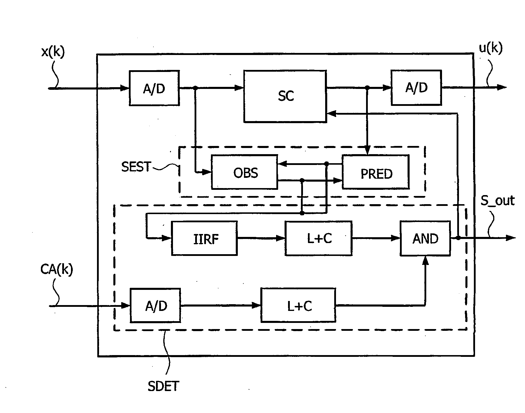
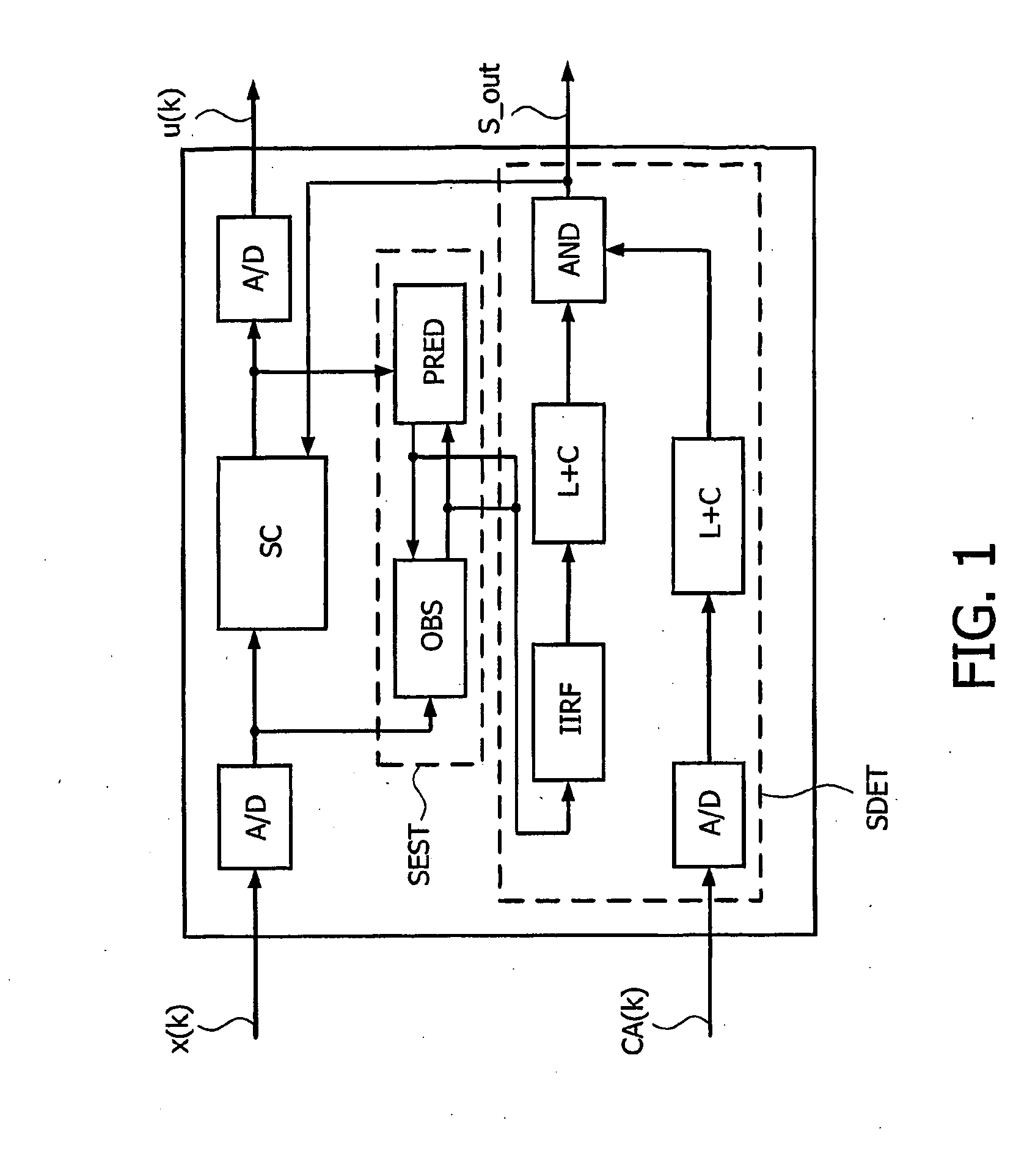
[0013]The present invention is based on the fact that the sum signal derived from the optical sensor remains at the same level during a shock and in the absence of shock. But during disc defects, said sum signal either drops or increases due to a decrease or increase, respectively, of light intensity reflected by a disc and caused by the disc defects. As a consequence, occurrence of a shock can be accurately and promptly detected thanks to the estimated radial error signal, the predicted radial error signal, and said sun signal.

Problems solved by technology

However, increasing servo loop bandwidth increases the loop sensitivity to noise such as disc defects in the low frequency range.
However, this method is not able to detect properly a sudden rise in the radial error signal caused by disturbances such as disc defects.
Moreover, it may not be fast enough to let the servo controller react.

Method used


Image

  • Anti-Shock Optical Recording and Reproducing Device
  • Anti-Shock Optical Recording and Reproducing Device
  • Anti-Shock Optical Recording and Reproducing Device

Examples


Embodiment Construction

[0022]The present invention proposes an optical recording and reproducing device (e.g. an optical drive), which is more robust to shock.

[0023]In an embodiment of the optical recording and reproducing device according to the invention, the device comprises an optical pick-up unit movably mounted on positioning means for roughly positioning the optical pick-up unit with respect to a desired position on a disc. The positioning means is usually implemented by a sledge. The optical pick-up unit includes a semiconductor laser for delivering a laser beam, an objective lens focusing the laser beam on the disc and an optical sensor (e.g. laser diodes) detecting the light reflected from said disc. The optical sensor is divided into at least two regions, a front half region and a rear half region. As an example, the optical sensor is divided into four regions, two regions being arranged to receive light reflected from the front half of a laser spot formed on the disc while the two other region...


PUM

PropertyMeasurementUnit
frequencyaaaaaaaaaa
clock frequencyaaaaaaaaaa
frequencyaaaaaaaaaa

Abstract

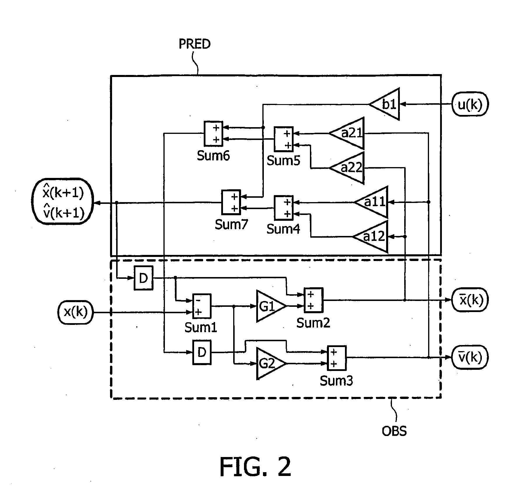
The present invention relates to an optical recording and reproducing device comprising an optical pick-up unit, position means for moving roughly the optical pick-up unit with respect to a desired position on an optical disc, an actuator for moving the optical pick-up unit relative to the position means in a radial direction of the optical disc, and a servo processor for delivering a control signal (u(k)) from a measured radial error signal (x(k)) derived from the optical pick-up unit. Said servo processor further comprises: —a state estimator (SEST) for delivering an estimated radial error signal ( ) and a predicted radial error signal ( ) on the basis of the measured radial error signal (x(k)) and of the control signal (u(k)); and—a shock detector (SDET) for delivering a shock indication (S_out) on the basis of the estimated radial error signal, of the predicted radial error signal, and of a sum (CA(k)) of the signals delivered by the at least two regions of the optical sensor.

Description

FIELD OF THE INVENTION[0001]The present invention relates to an optical recording and reproducing device.[0002]The present invention further relates to a servo processor for use in an optical recording and reproducing device and a processing method for use in an optical recording and reproducing device.[0003]The present invention may be used, for example, in optical data drives, portable and mobile applications and recordable drives (CDRW, DVDRW) where the anti-shock performance is of great importance.BACKGROUND OF THE INVENTION[0004]There are conventionally two ways of improving the optical drive's anti-shock performance, the first one through mechanism suspension design and the second one through shock robustness improvement of servo system.[0005]Conventional suspension design can efficiently absorb influence of shock in the low frequency range, usually below 100 Hz. But the disturbance influence to the tracking performance at a comparatively higher frequency range has also to be ...

Claims


Application Information

Patent Timeline
Patent Type & Authority Applications(United States)
IPC IPC(8): G11B7/00G11B7/09
CPCG11B7/0948G11B7/0946G11B7/09G11B33/08
Inventor ZHOU, YU
Owner KONINKLIJKE PHILIPS ELECTRONICS NV
Learn More