
Control apparatus for vehicular drive system

a control apparatus and vehicular drive technology, applied in the direction of analogue processes, instruments, gearing, etc., can solve the problems of generating a shifting shock, learning control does not necessarily and the requirement for a long time, so as to achieve a high control response and prevent or reduce the risk of generation.

Inactive Publication Date: 2008-09-25
TOYOTA JIDOSHA KK
View PDF6 Cites 21 Cited by
  • Summary
  • Abstract
  • Description
  • Claims
  • Application Information

AI Technical Summary

Benefits of technology

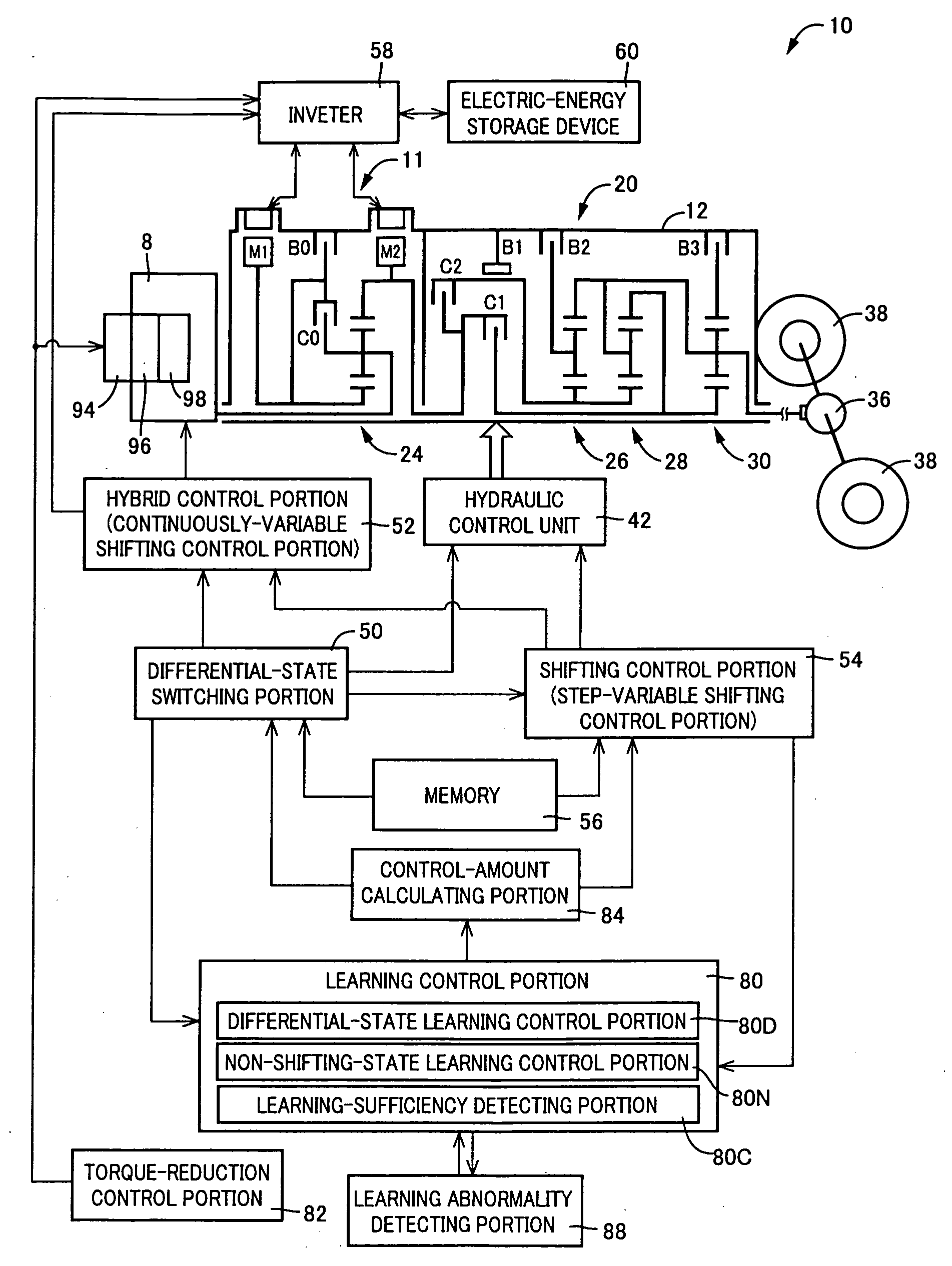
[0009]The present invention was made in view of the background art described above. It is therefore an object of the present invention to provide a control apparatus for a vehicular drive system including an electrically controlled differential portion switchable between a differential state and a non-differential state, and a transmission portion having a plurality of coupling devices, which control apparatus comprises a differential-state switching portion to switch the differential portion between the differential and non-differential states, a shifting control portion to control a shifting action of the transmission portion, and a learning control portion to effect learning compensation of a control amount of a control element to be controlled during the shifting action of the transmission portion, the control apparatus being configured to implement a learning control of the shifting action depending upon a selected one of the differential and non-differential states of the differential portion, and to implement an adequate control of the shifting action of the transmission portion so as to prevent or reduce a risk of generation of a shifting shock of the transmission portion even in the event of a failure or insufficiency of the learning control.

Problems solved by technology

In the presence of variations of the step-variable transmission with respect to nominal specification, the step-variable transmission has a risk of generation of a shifting shock if the shifting action is performed at a nominal point of shifting.
If the learning control of the shifting action of the transmission portion is implemented in a predetermined manner irrespective of the presently selected one of the differential and non-differential states of the differential portion, that is, without taking account of the presently established differential or non-differential state of the differential portion, the learning control does not necessarily prevent or reduce the risk of shifting shock of the transmission portion, due to a difference between the differential and non-differential states of the electrically controlled differential portion.
In this case, however, the manner of the learning control frequently changes upon a change of the operating state from one state to the other, so that the time allowed for each opportunity of the learning control tends to be short, giving rise to a requirement for a long length of time for a satisfactory or successful result of the learning control, whereby the transmission portion may suffer from a shifting shock until the satisfactory result of the learning control is obtained.

Method used


Image

  • Control apparatus for vehicular drive system
  • Control apparatus for vehicular drive system
  • Control apparatus for vehicular drive system

Examples


Embodiment Construction

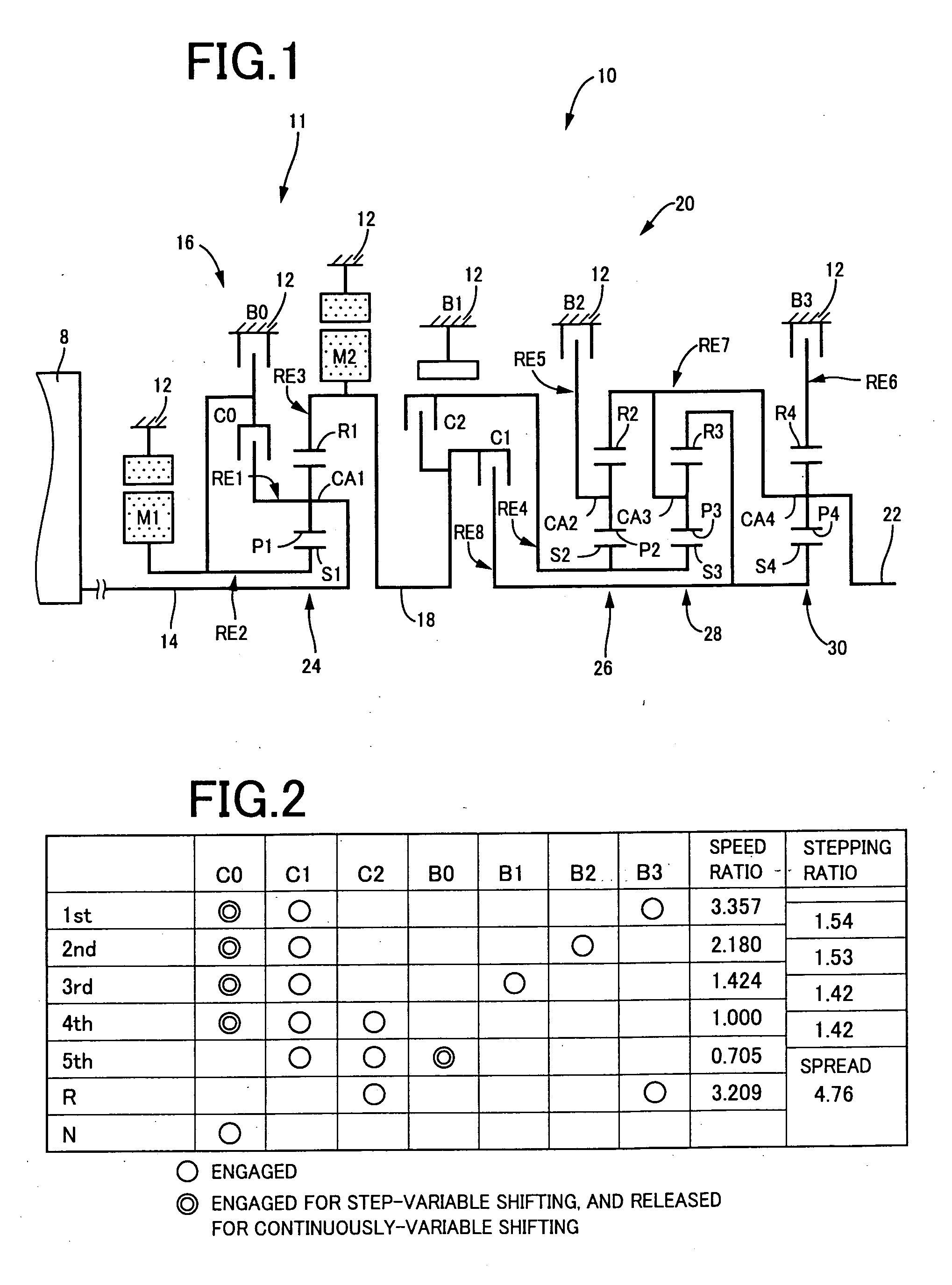
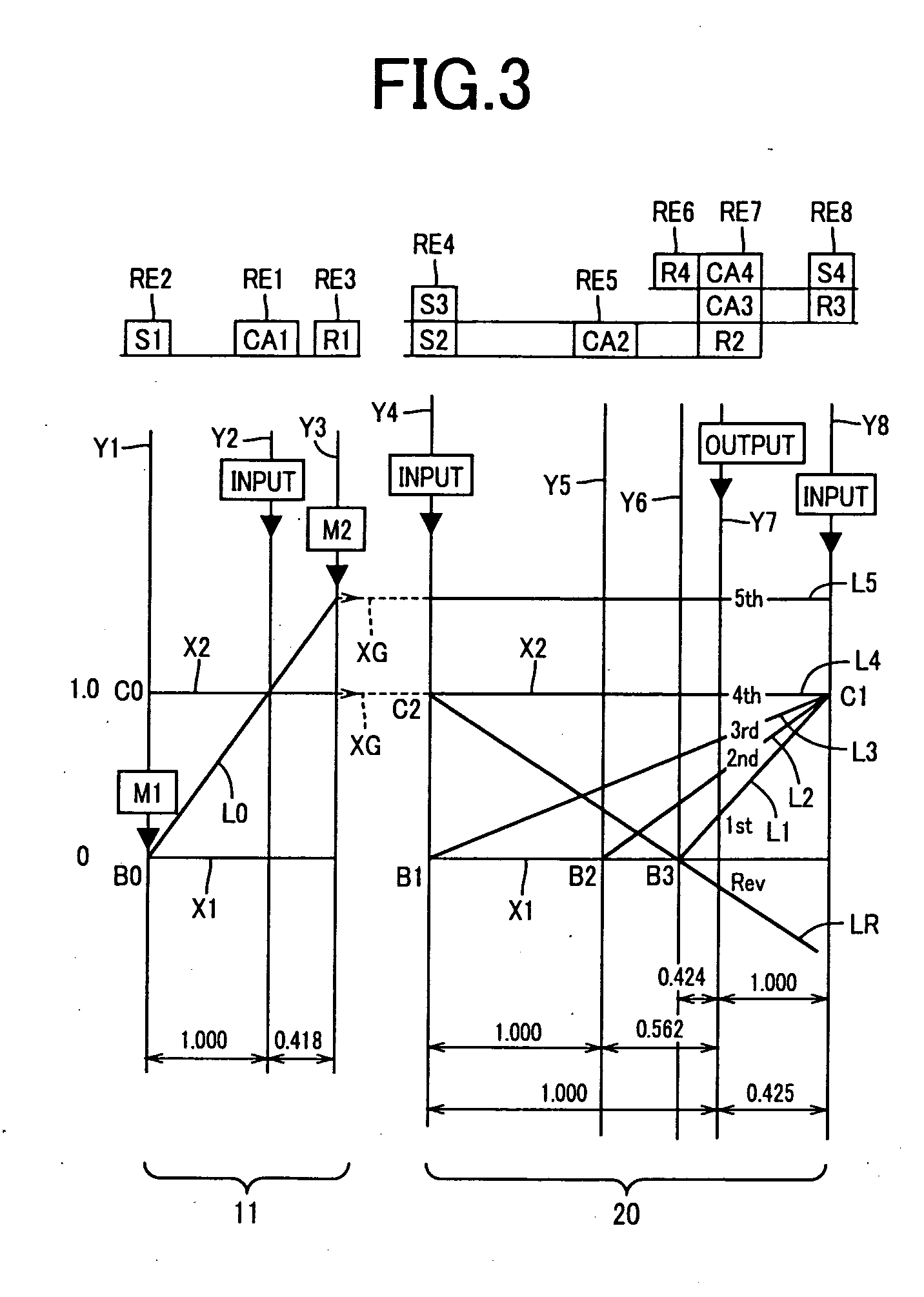
[0057]Referring first to the schematic view of FIG. 1, there is shown a transmission mechanism 10 constituting a part of a drive system for a hybrid vehicle, which drive system is controlled by a control apparatus constructed according to one embodiment of this invention. In FIG. 1, the transmission mechanism 10 includes: an input rotary member in the form of an input shaft 14; an electrically controlled differential portion in the form of a continuously-variable transmission portion 11 connected to the input shaft 14 either directly, or indirectly via a pulsation absorbing damper (vibration damping device) not shown; a step-variable or multiple-step transmission portion in the form of a step-variable transmission portion 20 disposed between the continuously-variable transmission portion 11 and drive wheels 38 of the vehicle, and connected in series via a power transmitting member 18 (power transmitting shaft) to the transmission portion 11 and the drive wheels 38; and an output rot...


PUM


Abstract

A control apparatus for a vehicular drive system including an electrically controlled differential portion having a differential mechanism, and an electric motor which is operatively connected to the differential mechanism and an operating state of which is controlled to control a differential state between input and output shaft speeds, and a transmission portion constituting a part of a power transmitting path between the differential portion and a vehicle drive wheel, the control apparatus including a differential-state switching portion for switching the differential portion between differential-state and non-differential states, a shifting control portion for controlling a shifting action of the transmission portion, and a learning control portion for effecting learning compensation of a control amount of a control element to be controlled during the shifting action, wherein the learning control portion includes a differential-state learning control portion operable to implement the learning compensation of the control amount of the control element when the shifting action takes place in the differential state of the differential portion, and a non-differential-state learning control portion operable to implement the learning compensation when the shifting action takes place in the non-differential state of the differential portion, and the shifting control portion controls the shifting action in a presently selected one of the differential and non-differential states of the differential portion, on the basis of the learning compensation implemented by one of the differential-state and non-differential-state learning control portions which is operable in the other of the differential and non-differential states of the differential portion.

Description

[0001]The present application claims priority from Japanese Patent Application No. 2007-071339 filed Mar. 19, 2007, the disclosure of which is herein incorporated by reference in its entirety.BACKGROUND OF THE INVENTION[0002]1. Field of the Invention[0003]The present invention relates in general to a control apparatus for a vehicular drive system, and more particularly to shifting control of the vehicular drive system by the control apparatus according to a selected one of two different operating states of the vehicular drive system.[0004]2. Discussion of Prior Art[0005]There is known a control apparatus for a vehicular drive system including an electrically controlled differential portion, a transmission portion, and a differential-state switching device configured to switch a differential mechanism of the electrically controlled differential portion between a differential-state in which the differential portion is operable to perform a differential function, and a non-differential...

Claims


Application Information

Patent Timeline
Patent Type & Authority Applications(United States)
IPC IPC(8): G06F19/00B60K6/365B60K6/445B60K6/543B60K6/547B60L15/20B60W10/04B60W10/06B60W10/08B60W10/10B60W10/105B60W10/11B60W10/115B60W20/00F16H59/14F16H59/42F16H61/04F16H61/68F16H61/684F16H61/686F16H63/50
CPCB60K1/02Y10T477/26B60K6/445B60K6/547B60W10/06B60W10/08B60W10/115B60W20/00F16H3/728F16H2037/0873Y02T10/6286Y02T10/7258Y02T10/6239Y10T477/6243B60K6/365Y02T10/62Y02T10/72B60W10/10
Inventor TABATA, ATSUSHIMATSUBARA, TOORUIWASE, YUJISHIBATA, HIROYUKI
Owner TOYOTA JIDOSHA KK
Learn More