Surgical stapling and cutting instrument with side mounted retraction member

a technology of retraction member and surgical stapling, which is applied in the field of surgical stapling and cutting instruments with side mounted retraction members, can solve the problems of incomplete firing, binding or other malfunction, and cannot effectively form closed staples in the severed tissu

Active Publication Date: 2008-10-02
CILAG GMBH INT
View PDF99 Cites 440 Cited by
  • Summary
  • Abstract
  • Description
  • Claims
  • Application Information

AI Technical Summary

Benefits of technology

[0011]In one aspect of the invention, there is provided a surgical instrument has a handle assembly and an end effector for performing a surgical operation. The end effector may be operably coupled to the handle assembly and may operably support a firing member that is movable from a retracted position to a fired position in response to a longitudinal firing motion applied thereto. The instrument may also include a firing drive that is supported by the handle assembly and is co

Problems solved by technology

Otherwise, opposing jaws may be drawn too close together, especially pinching at their distal ends, and thus not effectively forming closed staples in the severed tissue.
At the other extreme, an excessive amount of clamped tissue may cause binding and an incomplete firing.
In addition, some surgeons, not familiar with the larger staple cartridges, may become concerned that binding or other malfunction has occurred when an unexpectedly higher force is required.
These known surgical stapling instruments with multiple-stroke firing mechanisms do not have the advantages of a separate closure and firing actions

Method used


Image

  • Surgical stapling and cutting instrument with side mounted retraction member
  • Surgical stapling and cutting instrument with side mounted retraction member
  • Surgical stapling and cutting instrument with side mounted retraction member

Examples


Embodiment Construction

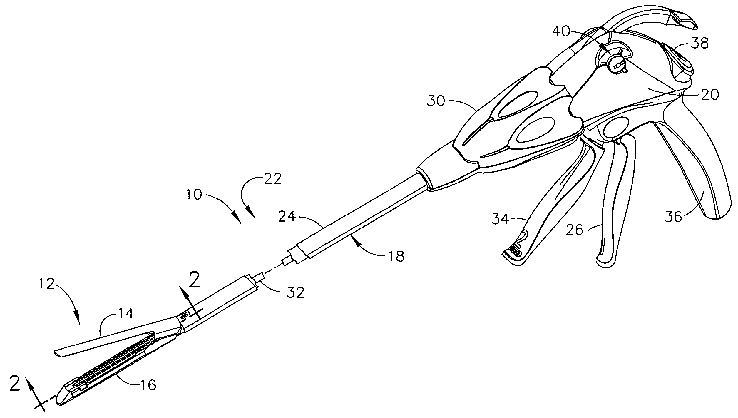
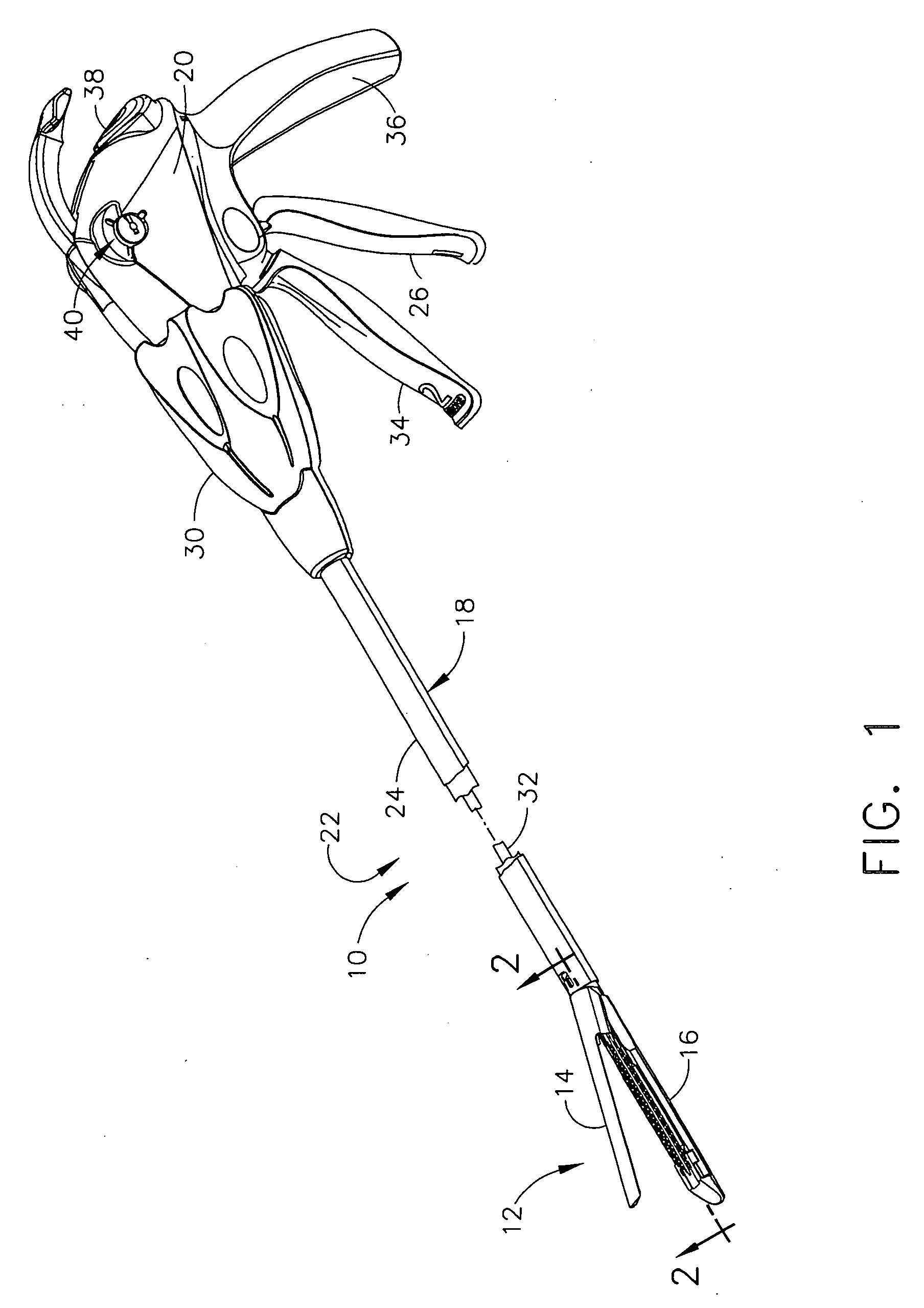
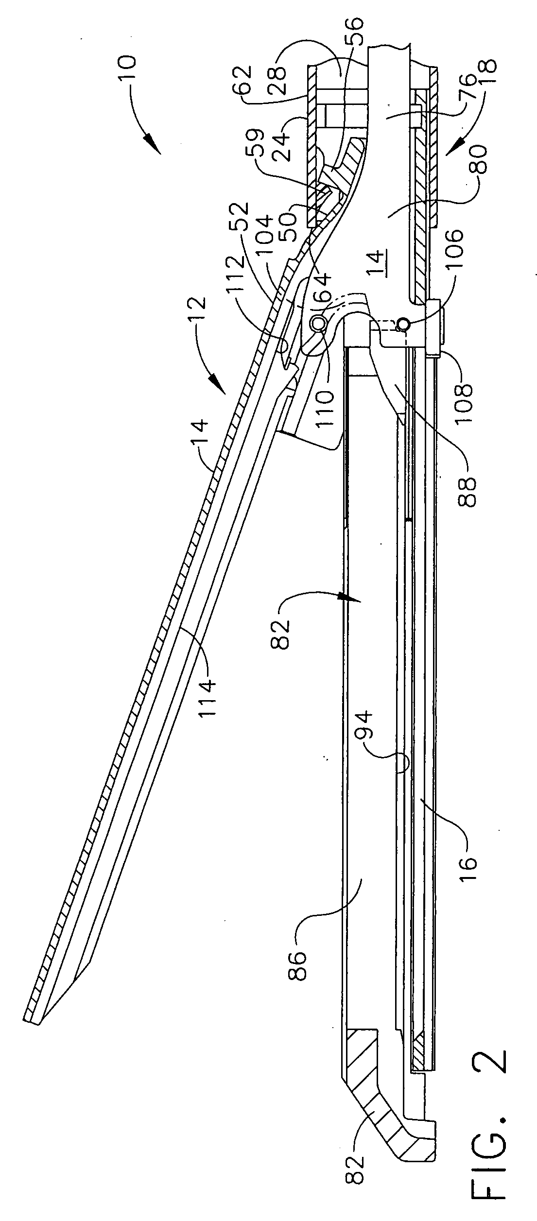
[0043]Turning to the Drawings, wherein like numerals denote like components throughout the several views, FIGS. 1 and 2 depict a surgical stapling and severing instrument 10 that is capable of practicing the unique benefits of the present invention. The surgical stapling and severing instrument 10 incorporates an end effector 12 having an anvil 14 pivotally attached to an elongate channel 16, forming opposing jaws for clamping tissue to be severed and stapled. The end effector 12 is coupled by an elongate shaft assembly 18 to a handle 20 (FIG. 1). An implement portion 22, formed by the end effector 12 and shaft assembly 18, is advantageously sized for insertion through a trocar or small laparoscopic opening to perform an endoscopic surgical procedure while being controlled by a surgeon grasping the handle assembly 20. The handle assembly 20 advantageously includes features that allow separate closure motions and firing motions, lockouts to prevent inadvertent or ill-advised firing o...


PUM

PropertyMeasurementUnit
Lengthaaaaaaaaaa
Forceaaaaaaaaaa

Abstract

A surgical stapling and severing instrument particularly suited to endoscopic procedures incorporates a handle that produces separate closing and firing motions to actuate an end effector. In particular, the handle produces multiple firing strokes in order to reduce the required amount of force required to fire (i.e., staple and sever) the end effector. A linked transmission reduces the required handle longitudinal length, yet achieves a rigid, strong configuration when straightened for firing. A traction biased firing mechanism avoids binding in driving this straightened linked rack. The instrument further has a manually actuatable retraction system that does not require the use of additional springs or other mechanisms to generate retraction forces which must be overcome when generating the forces necessary to fire the device. In various embodiments, the retraction system provides a visual indication to the surgeon as to how far firing has progressed.

Description

CROSS REFERENCE TO RELATED APPLICATIONS[0001]The present application is related to commonly-owned U.S. Pat. Application filed on even date herewith, entitled “Surgical Stapling and Cutting Instrument With Manually Retractable Firing Member” to Christopher J. Schall and Chad P. Boudreaux, the disclosure of which is hereby incorporated by reference in its entirety.FIELD OF THE INVENTION[0002]The present invention relates in general to endoscopic surgical instruments including, but not limited to, surgical stapler instruments that are capable of applying lines of staples to tissue while cutting the tissue between those staple lines and, more particularly, to improvements relating to surgical stapler instruments and improvements in processes for forming various components of such surgical stapler instruments that have manual retraction capabilities.BACKGROUND OF THE INVENTION[0003]Endoscopic surgical instruments are often preferred over traditional open surgical devices since a smaller ...

Claims


Application Information

Patent Timeline
IPC IPC(8): A61B17/04
CPCA61B17/07207A61B2017/2925A61B2017/2923A61B17/2909
Inventor BOUDREAUX, CHAD P.SCHALL, CHRISTOPER J.
Owner CILAG GMBH INT
Why Eureka
Try Eureka