Head module, liquid discharge head, and liquid discharge apparatus

a liquid discharge head and head module technology, applied in the direction of printing, inking apparatus, etc., can solve the problems of increasing increasing the number of steps, increasing the complexity of the wiring structure, etc., and achieve the reduction of the number of wires in the terminal section and the width of the terminal section, and the space used for the connecting process. greatly reduced

Inactive Publication Date: 2008-10-02
SONY CORP
View PDF3 Cites 15 Cited by
  • Summary
  • Abstract
  • Description
  • Claims
  • Application Information

AI Technical Summary

Benefits of technology

[0027]In the above-described embodiments, the wiring board includes the connecting sections configured to connect the wires to the respective electrodes on the head chips in the respective head-chip lines, the common wire sections configured to join some of the wires that are common to the head chips in the respective head-chip lines, and the terminal section configured to connect the wires to the control substrate at one side of the wiring board. The wires in the connecting sections and the terminal section are arranged in a single-layer structure along a horizontal direction, and the wires in the common wire sections are arranged in a multi-layer structure in which portions of the wires are stacked in the vertical direction. Therefore, the common wires are joined together in the common wire sections having a multi-layer structure and disposed between the terminal section and the connecting sections. Accordingly, the number wires in the terminal section is reduced. The terminal section is disposed at one side of the wiring board.
[0028]According to the present invention, in the wiring board, the common wire sections having a multi-layer structure are placed between the terminal section connected to the control substrate and the connecting sections connected to the electrodes of the head chips. The wires common to the head chips are joined together by the common wire sections. Therefore, the number of wires in the terminal section and the width of the terminal section are reduced. In addition, the terminal section is disposed at one side of the wiring board. Therefore, the wiring board can be electrically connected to the control substrate by the thin terminal section disposed at one side of the wiring board. As a result, the space used for the connecting process can be greatly reduced.

Problems solved by technology

However, according to Patent Document 2, a large space is used for establishing connection between a control board and the electrodes on the head chips.
However, in such a case, the number of wires in each wiring board is increased, which leads to an increase in the width of the terminal sections.
Therefore, the wiring structure becomes complex and the number of steps is increased in the manufacturing process of the wiring board and the assembly process of the head module.
Thus, the processes become cumbersome.

Method used


Image

  • Head module, liquid discharge head, and liquid discharge apparatus
  • Head module, liquid discharge head, and liquid discharge apparatus
  • Head module, liquid discharge head, and liquid discharge apparatus

Examples


Embodiment Construction

[0044]An embodiment of the present invention will be described below with reference to the accompanying drawings.

[0045]A color inkjet printer will be described as a liquid discharge apparatus according to an embodiment of the present invention. The color inkjet printer is capable of discharging inks (liquids) of four colors: yellow (Y), magenta (M), cyan (C), and black (K). The color inkjet printer includes a line head 1 as a liquid discharge head according to an embodiment of the present invention, and the line head 1 includes head modules 10 as head modules according to an embodiment of the present invention.

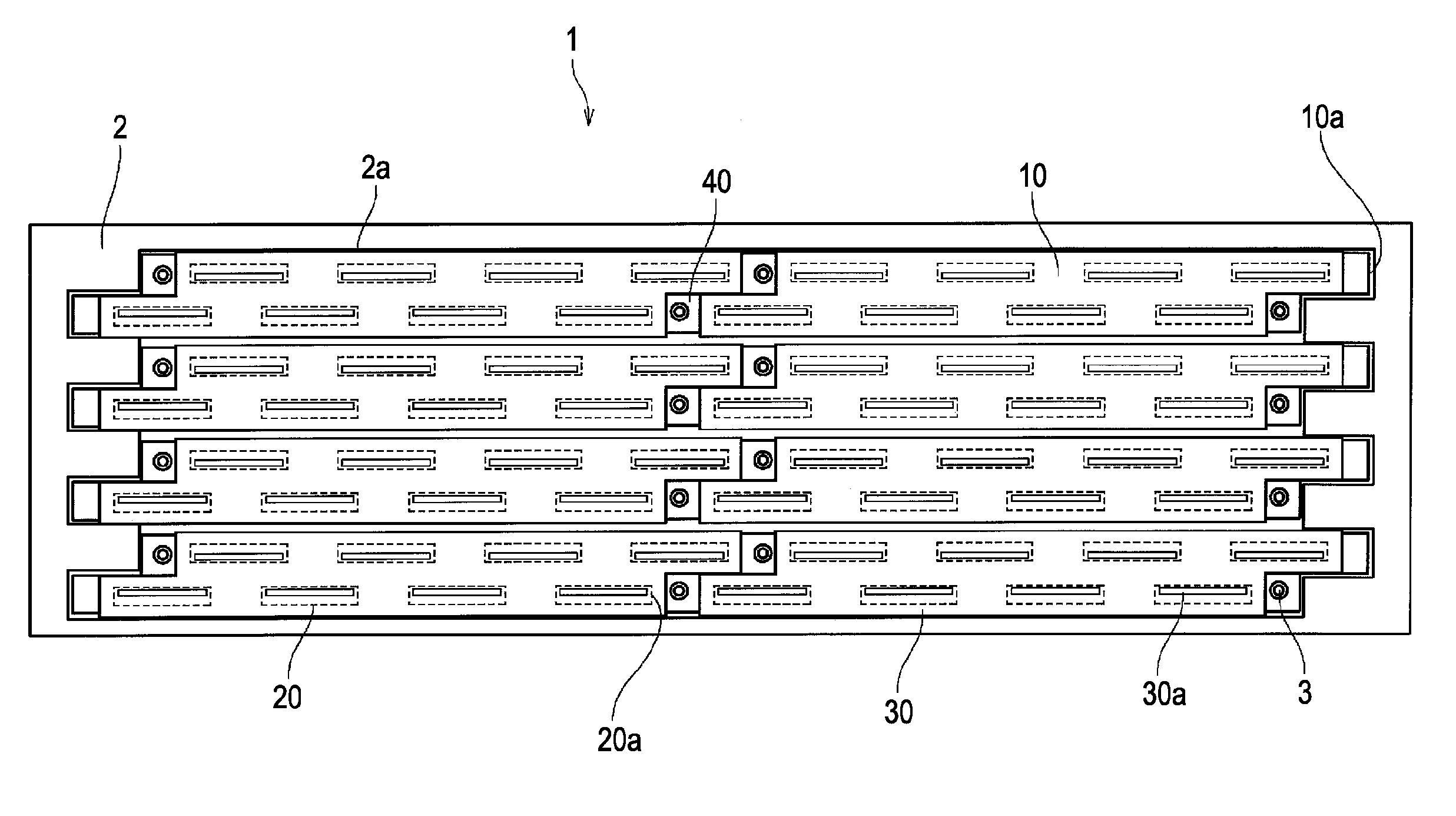
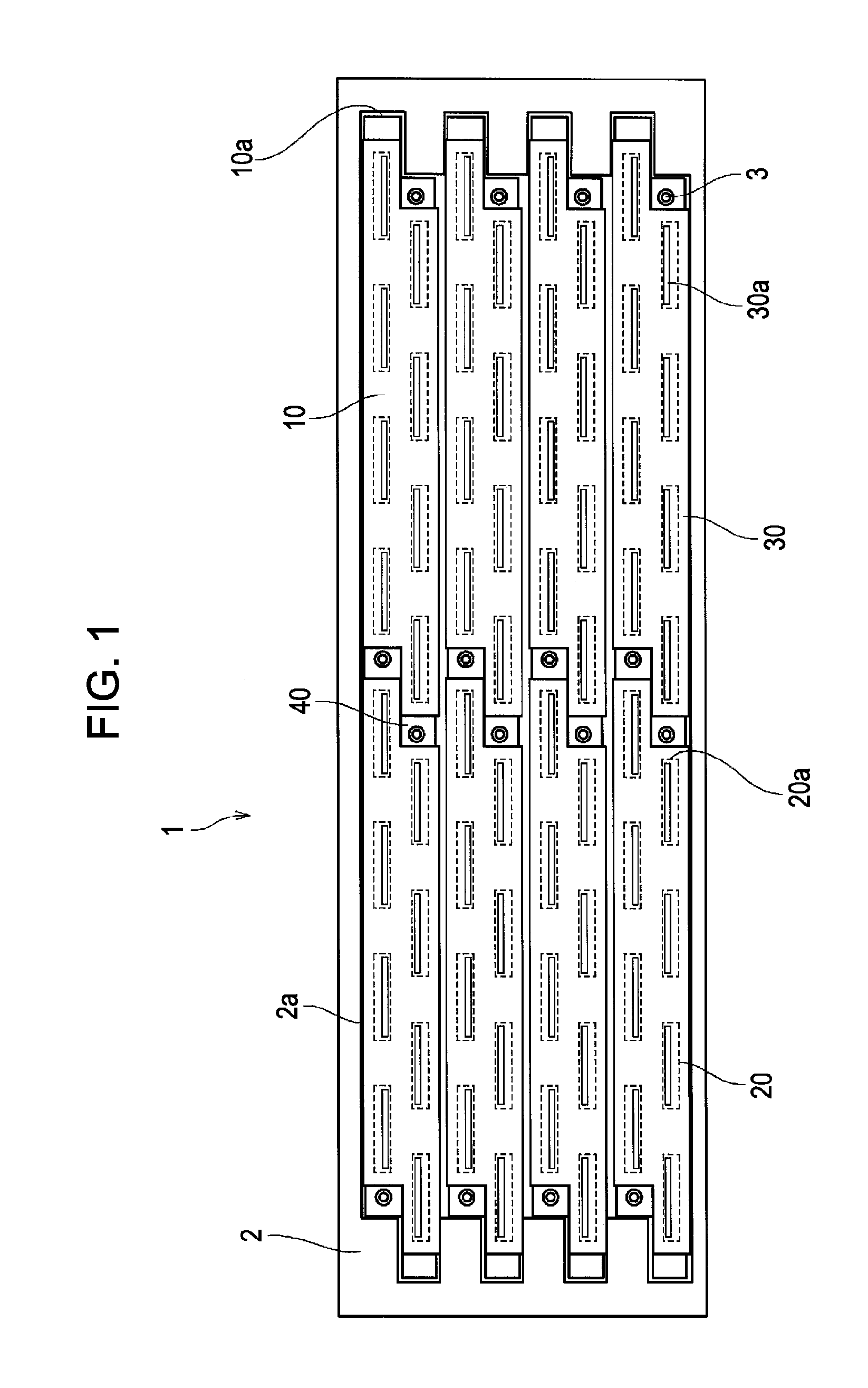
[0046]FIG. 1 is a plan view of the line head 1 according to an embodiment viewed from an ink discharge side.

[0047]Referring to FIG. 1, the line head 1 includes a plurality of head modules 10 fixed to a head frame 2 with screws 3. The head modules 10 are arranged so as to form four head-module lines 10a in a head-module receiving hole 2a in the head frame 2. Each head-module li...


PUM


Abstract

A head module includes lines of head chips, each head chip having energy-generating elements for discharging liquid and electrodes for electrically connecting the energy-generating elements to a control substrate, and a wiring board having wires for electrically connecting the electrodes to the control substrate. The head module drives the energy-generating elements through the wiring board to discharge liquid. The wiring board includes connecting sections connecting the wires to the respective electrodes, common wire sections joining some of the wires that are common to the head chips, and a terminal section connecting the wires to the control substrate at one side of the wiring board. The wires in the connecting and terminal sections are arranged in a single-layer structure along a horizontal direction. The wires in the common wire sections are arranged in a multi-layer structure in which portions of the wires are stacked in the vertical direction.

Description

CROSS REFERENCES TO RELATED APPLICATIONS[0001]The present invention contains subject matter related to Japanese Patent Application JP 2007-090859 filed in the Japanese Patent Office on Mar. 30, 2007, the entire contents of which are incorporated herein by reference.BACKGROUND OF THE INVENTION[0002]1. Field of the Invention[0003]The present invention relates to a head module for discharging liquid by driving energy-generating elements included in head chips via a wiring board, a liquid discharge head including a plurality of the head modules, and a liquid discharge apparatus including a plurality of the head modules. More particularly, the present invention relates to a technique for greatly reducing a space used for establishing connection to the wiring board.[0004]2. Description of the Related Art[0005]A line-head inkjet printer is an example of a liquid discharge apparatus in which nozzles for discharging ink (liquid) are arranged over a length corresponding to the width of a reco...

Claims


Application Information

Patent Timeline
Patent Type & Authority Applications(United States)
IPC IPC(8): B41J2/05
CPCB41J2/14072B41J2/1603B41J2/1623B41J2/1631B41J2/1632B41J2/1645B41J2202/20B41J2/04548
Inventor TOMITA, MANABUONO, SHOGOUSHINOHAMA, IWAOMURAKAMI, TAKAAKI
Owner SONY CORP
Why Eureka
Try Eureka