RF excited CO2 slab laser tube housing and electrodes cooling

a co2 slab laser and laser tube housing technology, applied in the direction of laser cooling arrangements, laser details, active medium materials, etc., can solve the problems of reducing the osub>2/sub>content of laser gas mixture, unable to use the laser tube housing hermetically sealed, and negatively affecting the laser's output performan

Active Publication Date: 2008-10-02
COHERENT INC
View PDF20 Cites 11 Cited by
  • Summary
  • Abstract
  • Description
  • Claims
  • Application Information

AI Technical Summary

Benefits of technology

[0012]A second aspect of the present invention provides a cooling system for the electrode assembly that is contained within the laser tube housing of a CO2 slab laser. This aspect of the present invention relies on a coolant fluid manifold system that is mounted on a longitudinal sidewall of the la

Problems solved by technology

The electrodes and the laser tube housing that contains the laser's electrodes, gas mixture and optical resonator are typically fabricated from Aluminum due to cost, good heat conduction and low weight.
Copper is a preferred cooling material, but it cannot be used within the hermetically sealed laser tube housing because it oxidizes, thereby reducing the O2 content of the laser gas mixture.
Having the electrode coolant pass through one of the end flanges presents a serviceability problem because the mirror(s) of the laser's optical resonator are mounted on the end flanges, one of which is also holding one end of the electrode assembly in place.
Since the mirrors of the optical resonator are typically mounted directly on the metal flanges, which are in turn directly mounted on the ends of the metal laser tube housing, the expansion and

Method used


Image

  • RF excited CO2 slab laser tube housing and electrodes cooling
  • RF excited CO2 slab laser tube housing and electrodes cooling
  • RF excited CO2 slab laser tube housing and electrodes cooling

Examples


Embodiment Construction

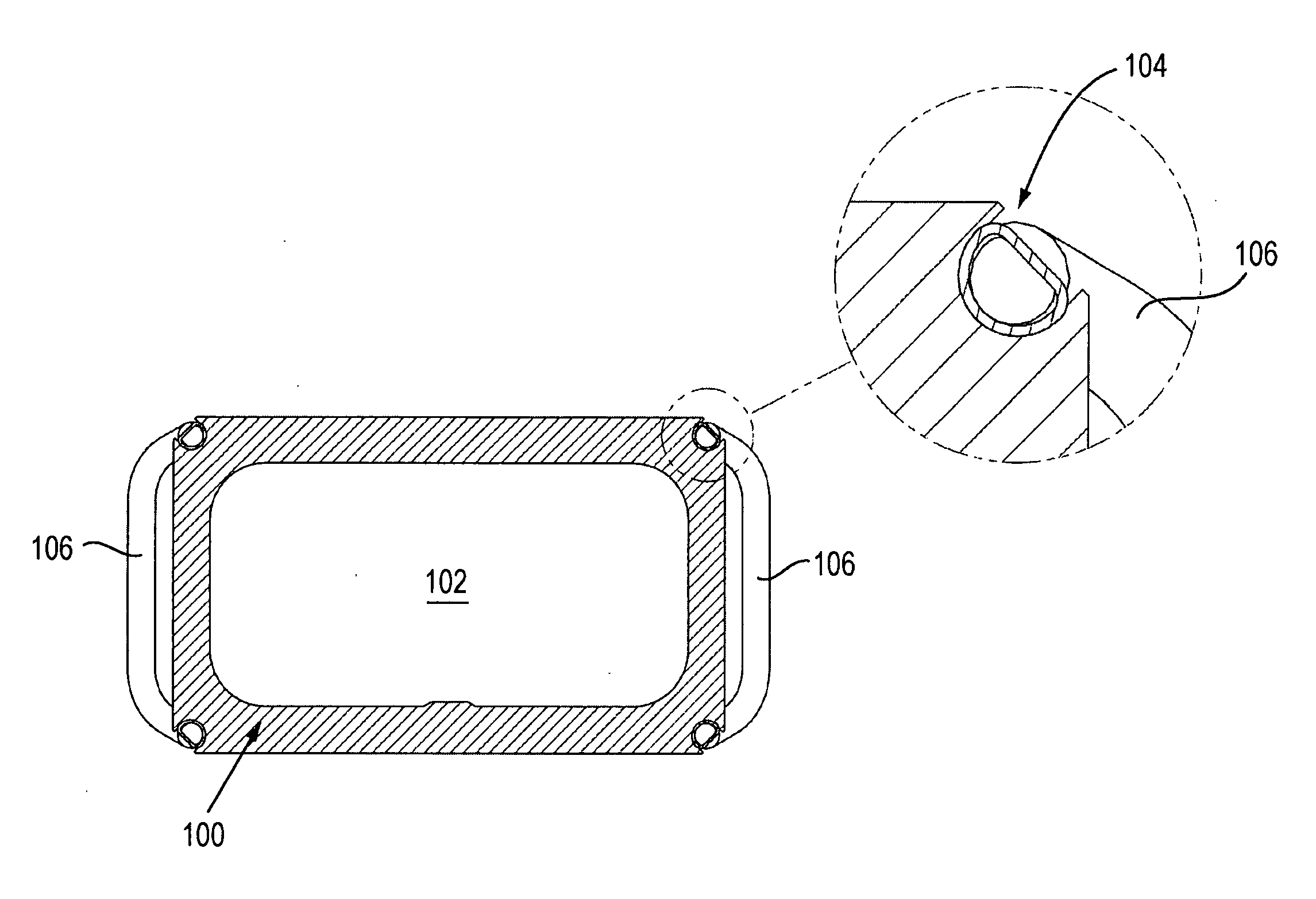
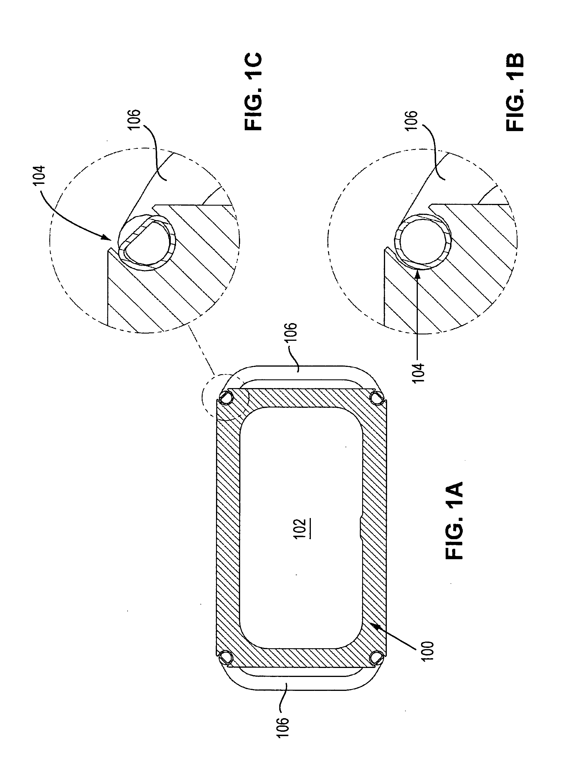
[0026]FIG. 1A shows a rectangular laser tube housing 100 for a 400 W output power, RF excited (i.e., typically at 100 MHz) CO2 slab laser. The interior 102 of the rectangular housing 100 will contain a typical CO2 mixture at a pressure of approximately 100 Torr, as well as the optical resonator and the electrode assembly, all in the well known manner. FIG. 1B shows one of the four hollowed out corners 104 of the rectangular housing structure 100 into which a properly sized copper cooling tube 106 is inserted in accordance with the concepts of the present invention. Since the edges of the rectangular laser tube housing 100 have more material then the flat surfaces, hollowing out the corners does not appreciably reduce the stiffness of the structure in comparison with the resulting stiffness if the hollowed out openings were placed on the flat surfaces of the structure, or if cooling passages were drilled within the flat surfaces of the laser tube housing, as in the prior art. FIG. 1C...


PUM


Abstract

The laser tube housing of a CO2 slab laser is provided with a cooling system in which coolant fluid tubes are inserted into hollowed out portions formed in the longitudinal sidewalls of the laser tube housing; mounting the coolant fluid tubes in this way provides for enhanced cooling and increased stiffness of the laser tube housing. Also, a cooling system is provided for the laser's electrode assembly that relies on a manifold system that is mounted on a longitudinal sidewall of the laser tube housing to route coolant fluid through the sidewall to the electrode assembly; sidewall flow of the coolant fluid enables the end flanges of the laser tube housing to be remove without disturbing either the electrodes or the optical resonator of the laser. Also, a bracket assembly is provided for attaching the laser's electrode assembly to a longitudinal sidewall of the laser tube housing; the bracket assembly includes two brackets each of which is attached to a respective end of the electrode assembly and each of which is also attached to a longitudinal sidewall of the laser tube housing in proximity to a respective longitudinal end of the laser tube housing.

Description

PRIORITY CLAIM[0001]This application claims priority from U.S. Provisional Application No. 60 / 920,680, filed Mar. 28, 2007, and titled “RF Excited CO2 Slab Laser Tube Housing and Electrode Cooling.” Provisional Application No. 60 / 920,680 is hereby incorporated by reference herein in its entirety.FIELD OF THE INVENTION[0002]The present invention relates generally to carbon dioxide (CO2) slab lasers and, in particular, to structures for cooling the laser tube housing and electrodes of a CO2 slab laser.BACKGROUND OF THE INVENTION[0003]The discharge of a RF excited CO2 slab laser is typically diffusion cooled. In diffusion cooled CO2 slab lasers, the excited (i.e., hot) CO2 molecules collide with the surfaces of the metal electrodes and become de-excited (i.e., cooled) by the collision and the transition to the ground state. In slab lasers, diffusion cooling is facilitated by providing a small separation (i.e., gap) between the parallel facing electrodes and by having the electrodes liq...

Claims


Application Information

Patent Timeline
IPC IPC(8): H01S3/041
CPCH01S3/0014H01S3/03H01S3/0407H01S3/041H01S3/2232
Inventor NEWMAN, LEON A.SHACKLETON, CHRISTIAN J.PAPANIDE, ADRIAN
Owner COHERENT INC
Why Eureka
Try Eureka