Headrest-mounted entertainment systems

a headrest and entertainment technology, applied in the field of entertainment systems, can solve the problems of various limitations and disadvantages of known units and various components thereo

Inactive Publication Date: 2008-10-09
VOXX INT CORP
View PDF99 Cites 20 Cited by
  • Summary
  • Abstract
  • Description
  • Claims
  • Application Information

AI Technical Summary

Benefits of technology

[0016]In another embodiment, a media system is provided that comprises an entertainment system configured to be mounted in a headrest of a vehicle. The entertainment system comprises a first cable coupled with a first connector. The media system further comprises a second cable coupled with a second connector, and the first and second connectors configured to couple with each other. The media system further comprises a retainer comprising a first interference surface and a second interference surface. The first and second interference surfaces are configured to substantially prevent axial movement of the first and second connectors relative to each other. The retainer further comprises at least a third interference surface configured to substantially prevent radial movement of the first and second connectors relative to each other. The retainer further comprises a fastener configured to permit the retainer to selectively couple with and decouple from the first and second connectors.
[0017]In certain embodiments, a mobile entertainment system comprises a housing configured to be mounted to a headrest. The housing can define a first hinge portion and a first lock portion. The first lock portion can have a first surface. In certain embodiments, the system further comprises a screen assembly including a viewing screen. The screen assembly can define a second hinge portion that cooperates with the first hinge portion to pivotally couple the screen assembly with the housing. The screen assembly can further define a second lock portion that comprises a manual interface. The second lock portion can cooperate with the first lock portion to selectively secure the screen assembly in substantially fixed relation to the housing. The second lock portion can have a second surface. In some embodiments, the first surface interferes with the second surface to prevent rotation of the screen assembly relative to the housing when the screen assembly is in a stowed position. In some embodiments, the manual interface is configured to move in a direction substantially parallel to a plane defined by the viewing screen in order to overcome interference of the first and second surfaces, thereby permitting the screen assembly to be rotated to a deployed position. Optionally, in some embodiments, the system comprises a headrest configured to be installed in a vehicle.
[0018]In certain embodiments, an entertainment system comprises a housing configured to be mounted to a headrest. The housing can define a first hinge portion, a base wall, and one or more sidewalls. The housing can include a lock portion. In some embodiments, the system comprises a screen assembly including a viewing screen. The screen assembly can define a second hinge portion that cooperates with the first hinge portion to pivotally couple the screen assembly with the housing. The screen assembly can further define an arm movable relative to the viewing screen. The arm can be configured to interact with the lock portion to retain the screen assembly in a stowed configuration in which the screen assembly is substantially prevented from moving away from the base wall of the housing. The arm further can be configured to be actuated to permit rotation of the screen assembly away from the base wall of the housing. In some embodiments, the system comprises a headrest configured to be installed in a vehicle.

Problems solved by technology

However, known units and various components thereof have various limitations and disadvantages.

Method used


Image

  • Headrest-mounted entertainment systems
  • Headrest-mounted entertainment systems
  • Headrest-mounted entertainment systems

Examples


Embodiment Construction

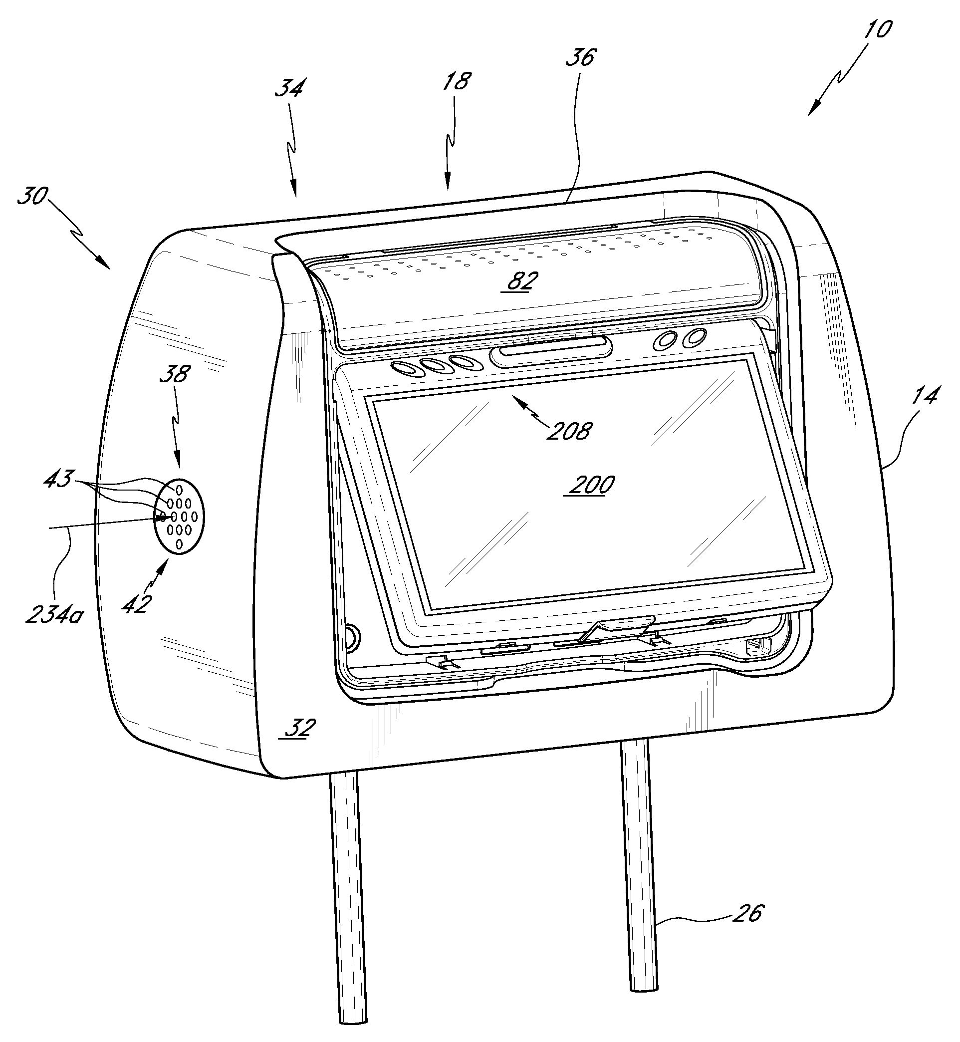
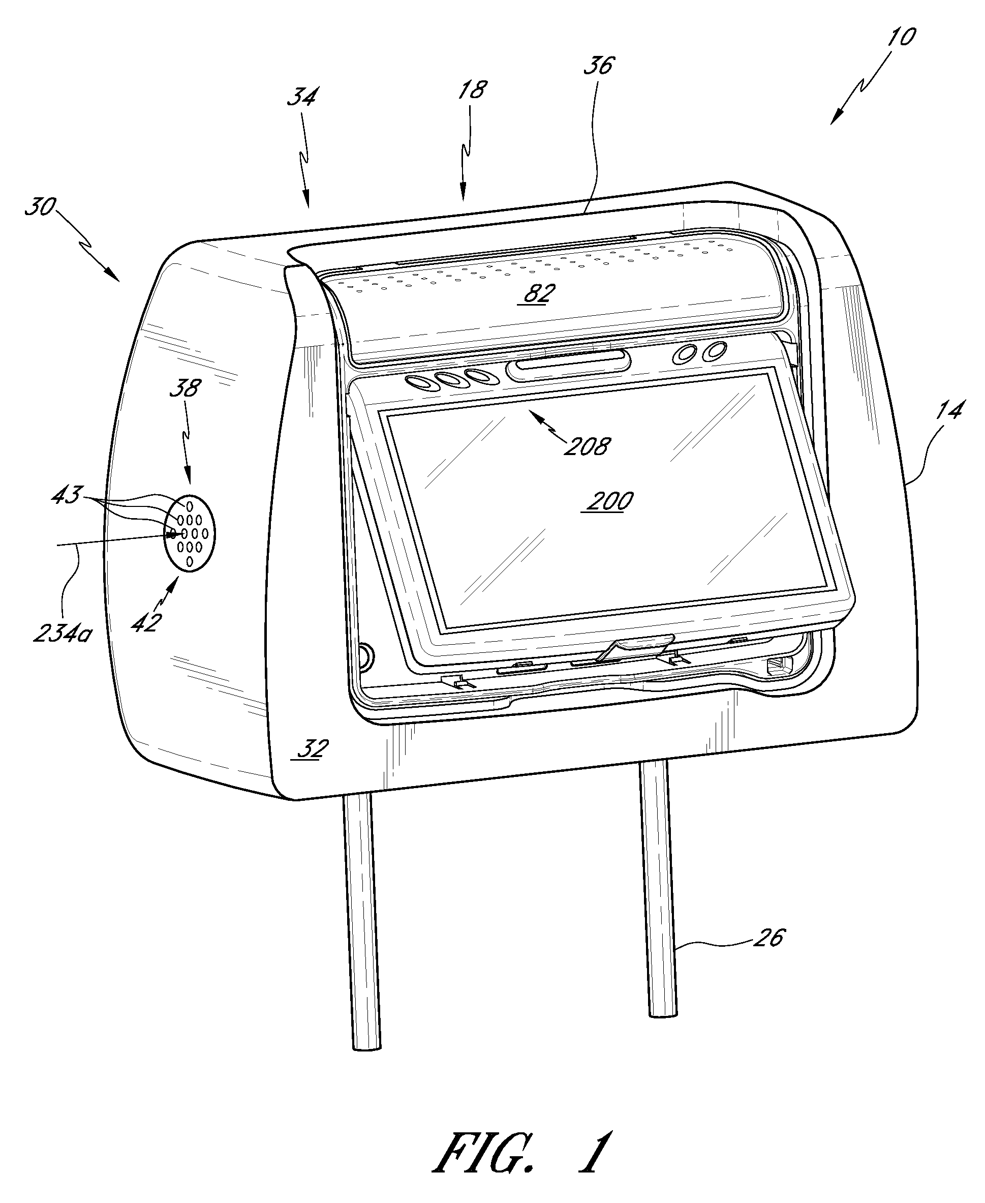
[0070]FIG. 1 shows one embodiment of a headrest entertainment assembly 10. The assembly 10 has a number of advantageous features. As discussed further below, the headrest entertainment assembly 10 and some variations thereof include a component cover that provides protection in connection with a signal source. Another feature of the assembly 10 and of some variations is a cooling system that keeps the components thereof from overheating. Further advantages of the assembly 10 and of some variations thereof reside in various inventive techniques for manufacturing the assembly 10, which techniques provide advantages associated with inventory control. Also, some embodiments of the assembly 10 and techniques for producing the assembly result in enhanced safety features for passengers in a vehicle in which the assembly 10 is mounted.

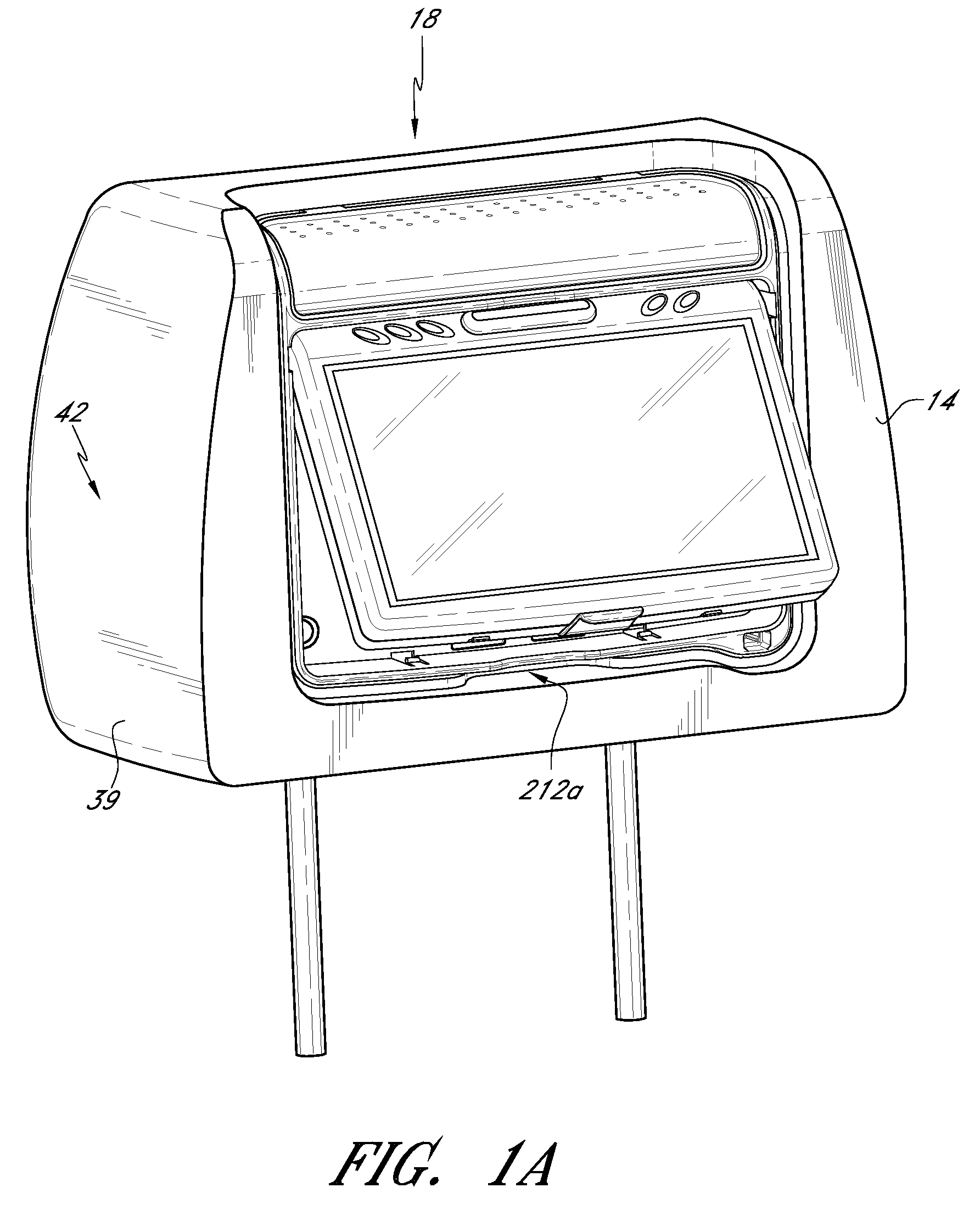
[0071]The headrest entertainment assembly 10 includes a vehicle headrest 14 and an entertainment system 18. Preferably the headrest entertainment assembly 10 ...


PUM


Abstract

In certain embodiments, an entertainment system includes a housing configured to be mounted to a headrest. The housing can define a first hinge portion, a base wall, and one or more sidewalls. The housing can include a lock portion. In some embodiments, the system includes a screen assembly including a viewing screen. The screen assembly can define a second hinge portion that cooperates with the first hinge portion to pivotally couple the screen assembly with the housing. The screen assembly can further define an arm movable relative to the viewing screen. The arm can be configured to interact with the lock portion to retain the screen assembly in a stowed configuration in which the screen assembly is substantially prevented from moving away from the base wall of the housing. The arm further can be configured to be actuated to permit rotation of the screen assembly away from the base wall of the housing. In some embodiments, the system includes a headrest configured to be installed in a vehicle.

Description

CROSS-REFERENCE TO RELATED APPLICATIONS[0001]This application is a continuation-in-part of U.S. application Ser. No. 11 / 475,735, filed Jun. 26, 2006, titled HEADREST MOUNTED ENTERTAINMENT SYSTEM, which claims the benefit under 35 U.S.C. §119(e) of U.S. Provisional Application No. 60 / 732,788, filed Nov. 2, 2005, titled HEADREST ENTERTAINMENT SYSTEM; U.S. Provisional Application No. 60 / 740,540, filed Nov. 29, 2005, titled HEADREST ENTERTAINMENT SYSTEM; and U.S. Provisional Application No. 60 / 811,879, filed Jun. 7, 2006, titled HEADREST MOUNTED ENTERTAINMENT SYSTEM. This application claims the benefit under 35 U.S.C. §119(e) of U.S. Provisional Application No. 60 / 912,157, filed Apr. 16, 2007, titled HEADREST-MOUNTED ENTERTAINMENT SYSTEMS. The entire contents of each of the above-identified applications are hereby incorporated by reference herein and made a part of this specification.BACKGROUND OF THE INVENTIONS[0002]1. Field of the Inventions[0003]This application relates to entertainm...

Claims


Application Information

Patent Timeline
Patent Type & Authority Applications(United States)
IPC IPC(8): A47C7/62
CPCB60R11/0235B60R11/0247B60R2011/0017B60R2011/0078
Inventor CHANG, CHUNG LUNG
Owner VOXX INT CORP
Why Eureka
Try Eureka