Electronic lock box with transponder based communications

a technology of electronic lock box and transponder, applied in the field of electronic lock box, can solve the problems of time delay between the actual showing event, significant deficit in the timeliness of information reported, and agents are required to use more cumbersome and expensive key devices to achieve the effect of announcing

Inactive Publication Date: 2008-10-09
SENTRILOCK
View PDF32 Cites 92 Cited by
  • Summary
  • Abstract
  • Description
  • Claims
  • Application Information

AI Technical Summary

Benefits of technology

[0006]Accordingly, it is an advantage of the present invention to provide an electronic lock box system used in real estate sales systems which provides a method of real time communication with a central clearinghouse computer of lock box system information, using a transponder in a dwelling base station to relay messages between the electronic lock box and the central clearinghouse computer.
[0007]It is another advantage of the present invention to provide an electronic lock box system used in real estate sales systems that overcomes the probable lack of timeliness in the communication infrastructure of the prior art systems, and instead provides the listing agent with the ability to ensure that timely data exchange occurs as their business needs dictate.
[0008]It is yet another advantage of the present invention to provide an electronic lock box system used in real estate sales systems which allows a real estate agent to remotely reprogram features of the electronic lock box without visiting the property where the particular lock box is currently located.
[0009]Additional advantages and other novel features of the invention will be set forth in part in the description that follows and in part will become apparent to those skilled in the art upon examination of the following or may be learned with the practice of the invention.
[0010]To achieve the foregoing and other advantages, and in accordance with one aspect of the present invention, an electronic lock box system is provided, which comprises: an electronic lock box having a first control circuit, a first memory circuit, a first communications circuit, a secure compartment with an access element, and a shackle for attachment to a fixed object; a dwelling base station having a second control circuit, a second memory circuit, a second communications circuit, and a third communications circuit; and an external apparatus having a third control circuit, a third memory circuit, and a fourth communications circuit; w...

Problems solved by technology

One inherent problem with this method is there often is a time delay between the actual showing event and the reporting of data to a centralized database.
Unfortunately, while this method marginally improves information exchange speed, there still could be a significant deficit in the timeliness of the information reported, due to the system inherently relying on the random actions of other agents in the system and the fact that this method essentially relies upon multiple showings in a very short period to be effective.
In the system described in this patent, agents are required to use more cumbersome and expensive key de...

Method used


Image

  • Electronic lock box with transponder based communications
  • Electronic lock box with transponder based communications
  • Electronic lock box with transponder based communications

Examples


Embodiment Construction

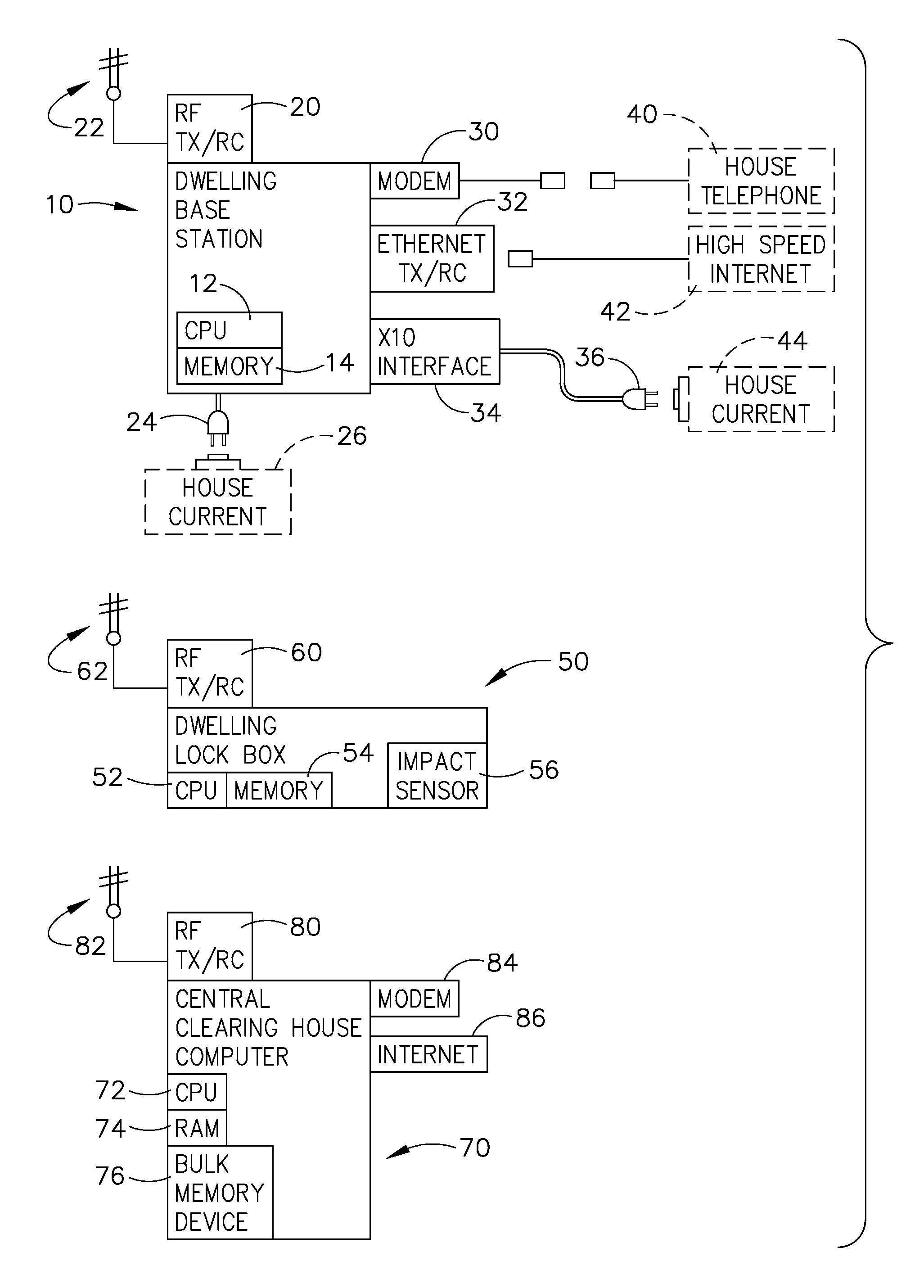
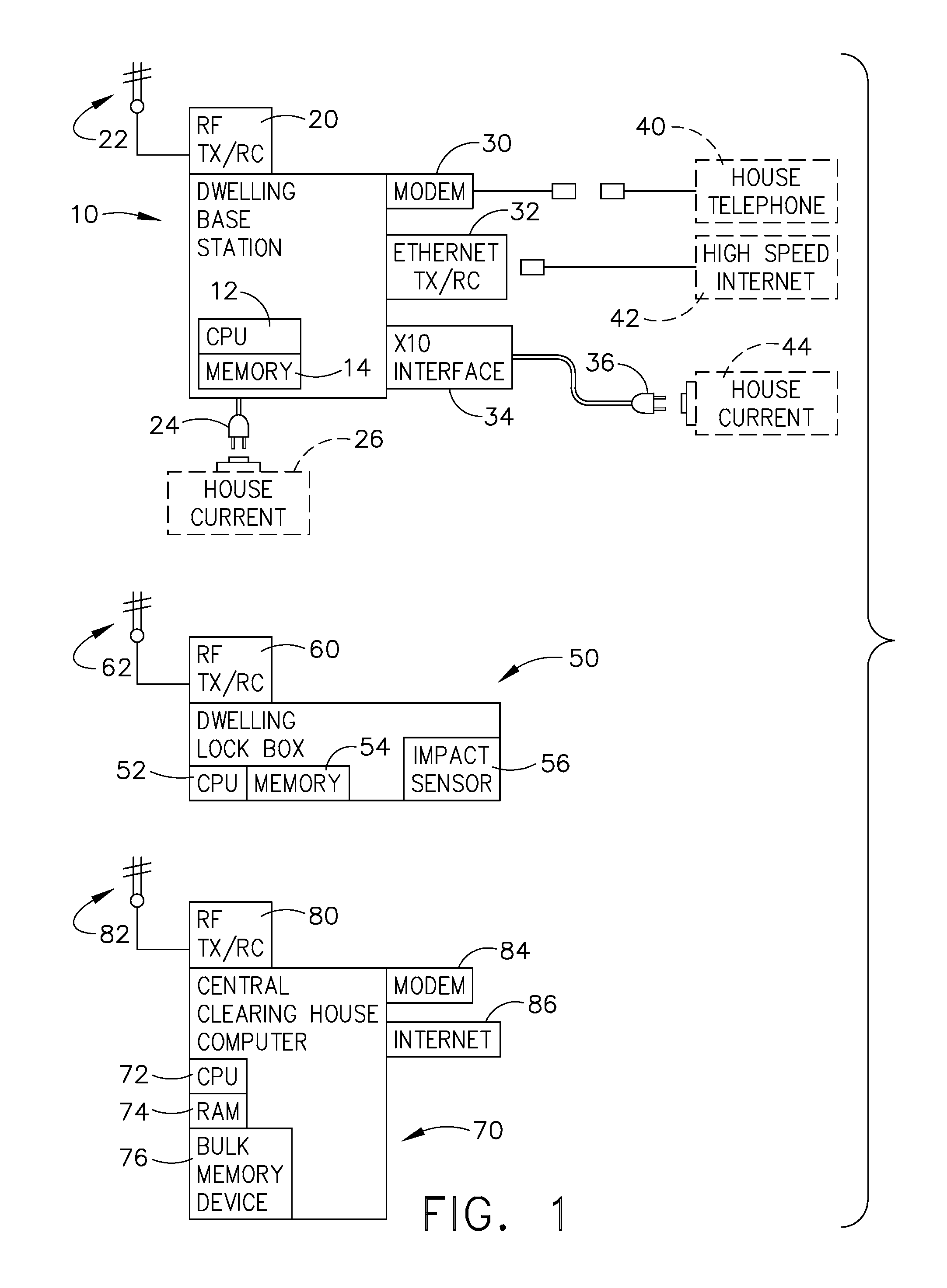
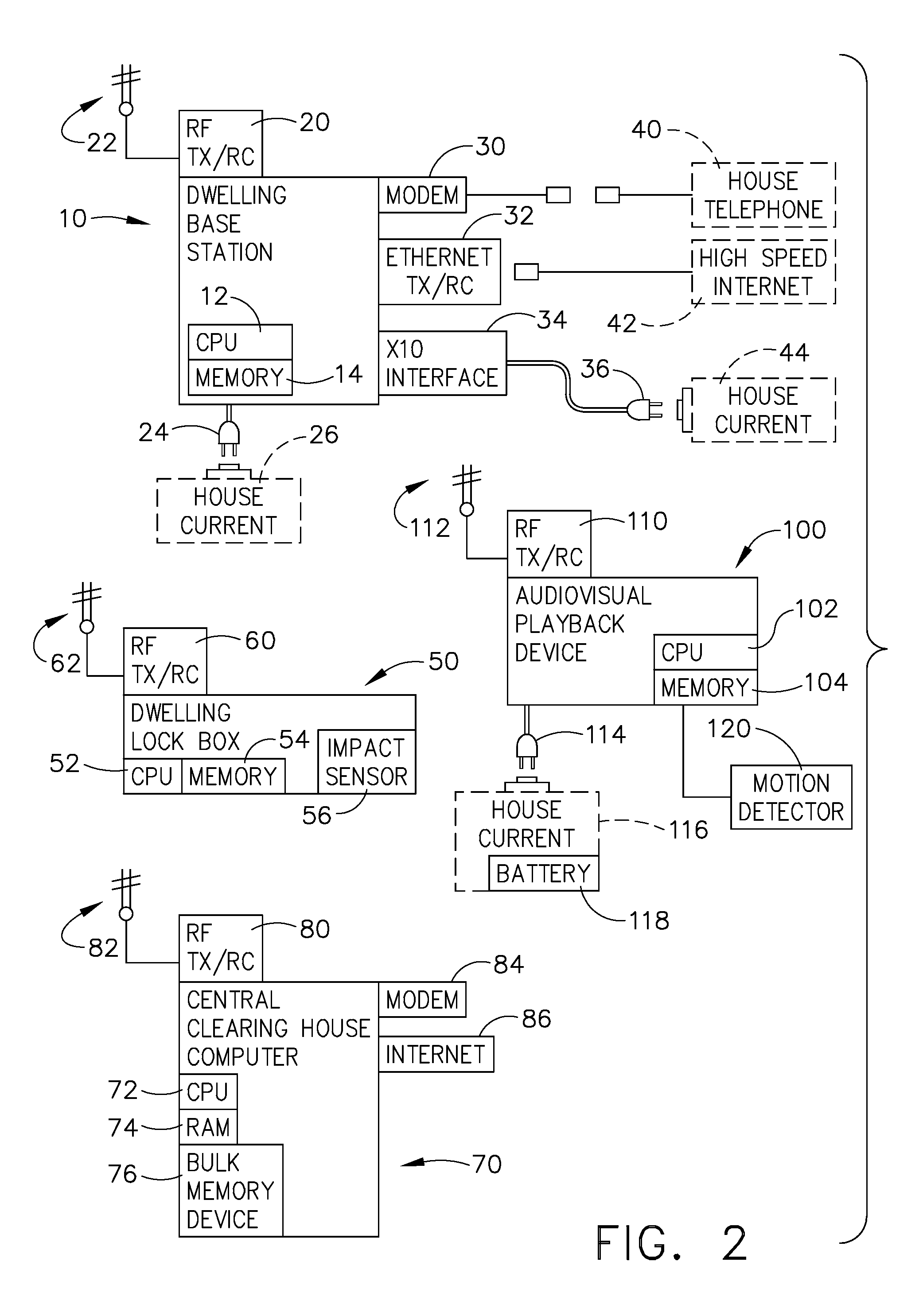
[0026]Reference will now be made in detail to the present preferred embodiment of the invention, an example of which is illustrated in the accompanying drawings, wherein like numerals indicate the same elements throughout the views.

[0027]The “basic” lock box invention, including advanced features, is more fully described in earlier patent documents by the same inventor, and assigned to SentriLock, Inc., including: U.S. Pat. No. 7,009,489, Issued Mar. 7, 2006, for ELECTRONIC LOCK SYSTEM AND METHOD FOR ITS USE; U.S. Pat. No. 6,989,732, Issued Jan. 24, 2006, for: ELECTRONIC LOCK SYSTEM AND METHOD FOR ITS USE WITH CARD ONLY MODE; U.S. Pat. No. 7,086,258; Ser. No. 10 / 805,020; Issued Aug. 8, 2006, for ELECTRONIC LOCK BOX WITH SINGLE LINEAR ACTUATOR OPERATING TWO DIFFERENT LATCHING MECHANISMS; U.S. patent application Ser. No. 10 / 805,018, filed on Mar. 19, 2004, for ELECTRONIC LOCK BOX WITH MULTIPLE MODES AND SECURITY STATES; U.S. patent application Ser. No. 11 / 193,932, filed on Jul. 29, 20...


PUM


Abstract

An electronic lock box contains a secure compartment for storing dwelling keys to a structure, and is typically mounted outside the dwelling structure. When properly instructed, usually with a coded message, the dwelling key can be accessed by opening the door to the secure compartment; such message can be manually entered on a keypad, or a programmed electronic key device can make the process more automatic. A lock box system uses a transponder at a dwelling base station (typically within the dwelling structure) to relay lock box status or access event information over a short range radio from the lock box to a remote central computer by using a more traditional communication system that is available within the dwelling. Additional sensors can be used to monitor the status of vandalism attempts. Furthermore, the lock box/transponder communications may be programmed so as to allow detection if the lock box is stolen.

Description

CROSS-REFERENCE TO RELATED APPLICATIONS[0001]The present application claims priority to provisional patent application Ser. No. 60 / 875,520, titled “ELECTRONIC LOCK BOX WITH TRANSPONDER BASED COMMUNICATIONS,” filed on Dec. 18, 2006.TECHNICAL FIELD[0002]The present invention relates generally to electronic lock equipment and is particularly directed to an electronic lock box of the type that contains a secure compartment for storing keys that allow entry to a structure or other objects. The invention is specifically disclosed as a system having an electronic lock box that includes a radio transmitter or transceiver that communicates to a central clearinghouse computer via an intermediate radio transponder to relay lock system information, in which the intermediate transponder is part of a dwelling base station. A radio communication message is sent to a local radio receiver (i.e., the transponder in the base station), and the communication message is further relayed to the central cle...

Claims


Application Information

Patent Timeline
IPC IPC(8): G05B19/00
CPCA47G29/10E05B19/0005E05B45/06E05B2047/0058E05B2047/0094G07C9/00571
Inventor FISHER, SCOTT R.
Owner SENTRILOCK
Why Eureka
Try Eureka