
Method of detecting lock bumping

a technology of lock bumping and detection method, which is applied in the field of security systems, can solve the problems of poor lock bumping, high cost of option, and inability to reimburse homeowners for losses,

Inactive Publication Date: 2008-10-09
HONEYWELL INT INC
View PDF6 Cites 21 Cited by
  • Summary
  • Abstract
  • Description
  • Claims
  • Application Information

AI Technical Summary

Benefits of technology

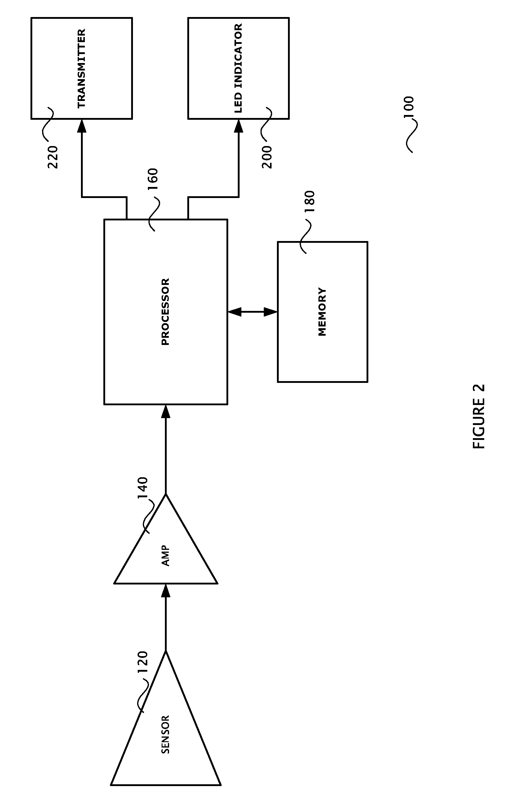
[0011]The present invention is a method of detecting a lock bumping procedure and notifying an authorized person (e.g. a homeowner or business owner, or a central station operator) that the lock bumping procedure has occurred. The method includes placing a lock bumping detection device on or in a door near the door lock, or on or in a door jamb near the door lock. The lock bumping detection device includes a sensor such as an acoustic sensor which senses acoustic energy (e.g. a microphone), a shock sensitive transducer (e.g. a MEMs accelerometer), o

Problems solved by technology

This technique has been a closely held secret of locksmiths for years, and the release of this information is a security issue to everyone who uses a pin tumbler lock, which is a lock that is opened with a metal key.
When no key or the wrong key is in the lock, the springs pushes against the drive pins causing the shearline to be misaligned due to the different sizes of the key pins, which prevents the cylinder from being turned.
Lock bumping is worse than a typical house break-in because when there is no evidence of a break-in the insurance companies may claim that the door was left unsecured by the homeowner.
As a result, the insurance companies are not reimbursing the homeowner for their losses.
This option is expensive and may not be desirable to the homeowner.
However, for homeowners that do not have an alarm system, forget to enable their alarm system, or have an alarm system that is disabled automatically with the turning of the lock cylinder, lock bumping is a significant problem.

Method used


Image

  • Method of detecting lock bumping
  • Method of detecting lock bumping
  • Method of detecting lock bumping

Examples


Embodiment Construction

[0020]The preferred embodiments of the present invention will now be described with respect to the Figures. FIG. 1 shows a flow diagram of the method of the present invention. In step 10 a sensor is located near the lock either on or in the door or the door jamb. The sensor may for example be an acoustic sensor such as a microphone, a MEMs accelerometer, or a piezoelectric effect sensor. The sensor senses energy from a physical event such as acoustic energy, vibration, etc. (step 20). The sensed energy is converted by the sensor to electrical signals that are then processed to determine if the energy sensed is a result of an attempted lock bumping procedure. The signals from the sensor are first amplified (step 30) by a wideband low gain amplifier. The amplified signal is then filtered in step 40 by narrow-band digital or analog filters. In step 50, the detection of the attempted lock bumping takes place with reference to a set of qualifying rules and a set of disqualifying rules as...


PUM


Abstract

A method of detecting an attempted lock bumping and providing a notification that an attempted lock bumping has occurred. A lock bumping detection device is placed on or in a door or door jamb near the lock. The device includes a sensor which senses energy and generates a signal that is processed to determine if the energy is a result of a lock bumping procedure. The sensed energy is analyzed to generate a received energy signature, which is compared to a stored energy signature with respected to qualifying and disqualifying rules. If the result of the comparison is positive, this indicates that the energy sensed is a result of an attempted lock bumping procedure. In the event that it is determined that the energy is a result of an attempted lock bumping procedure, then an alarm signal may be transmitted to an associated alarm system.

Description

CROSS-REFERENCE TO RELATED APPLICATION[0001]This application claims filing priority from co-pending provisional application Ser. No. 60 / 922,596, filed on Apr. 9, 2007.TECHNICAL FIELD[0002]This invention relates to security systems, and in particular to a security system device that detects if a lock bumping procedure has been attempted on the lock of an entry door.BACKGROUND ART[0003]Recently, information about lock bumping, which is a lock picking technique, has been released in the media and documented on the Internet. This technique has been a closely held secret of locksmiths for years, and the release of this information is a security issue to everyone who uses a pin tumbler lock, which is a lock that is opened with a metal key. This technique requires very little skill level and can be used by anyone. The technique involves inserting a bump key into the lock and tapping the bump key one or more times with a mallet (or similar device) while applying a slight turning force to th...

Claims


Application Information

Patent Timeline
IPC IPC(8): E05B45/00
CPCG08B13/06
Inventor SMITH, RICHARD A
Owner HONEYWELL INT INC
Learn More