System and method of enhanced virtual reality

a virtual reality and enhanced technology, applied in the field of virtual reality, can solve the problems of users becoming disoriented, dizzy or nauseous in this virtual world, simply having perspective is not enough to simulate reality, and achieve the effect of reducing nausea and dizziness

Inactive Publication Date: 2008-10-09
INT BUSINESS MASCH CORP
View PDF2 Cites 33 Cited by
  • Summary
  • Abstract
  • Description
  • Claims
  • Application Information

AI Technical Summary

Benefits of technology

[0014]The technical effect provided is the overlaying of the real image and the virtual image resulting in the composite image, which is displayed at the head mounted display. This composite image provides a virtual reality experience without the lack of self-involvement feeling and is believed to significantly reduce the feeling of nausea and dizziness, all of which are commonly encountered in prior art systems.

Problems solved by technology

This has been due to a lack of self, i.e., grounding themselves in the virtual world, which can result in a lack of belief of the virtual experience to disorientation and nausea.
However, simply having perspective is not enough to simulate reality.
Users become disoriented, dizzy or nauseous in this virtual world because they have no notion of physical being in this virtual world.
This body, however, is poorly articulated as it can only move in relation to user's real body if there are tracking devices on each joint / body part, and looks little or nothing like the user's own clothing or skin tone.
Furthermore, subtle motion, e.g., closing fingers, bending elbow, etc., are typically not tracked, because such would require an impractical number of tracking devices.
Even with this virtual body, users have trouble identifying with the figure, and coming to terms with how their motion in the real world relates to the motion of the virtual figure.
When motion is introduced to the virtual experience, the notion of nausea, and disorientation is increased.
Though this technique allows the user to have a notion of self, by seeing their own body, in most cases, the task of combining these two images, i.e., one presented to each eye, in the brain causes the user a head-ache and in some cases nausea thus limiting most users time in the virtual space.
Also, with any type of projection technology, real life objects interfering with the light projection will cast shadows, which leave holes in the projected images, or causes brightness gradients.
This approach often has side effects, e.g., headaches and nausea, making it impractical for general population use, and long-term use.
In addition to the visual problems, the notion of depth is limited as well.
Thus the methods of interaction appear to be less natural.
Though the images appear to be more real, the user's interaction with the projected virtual environment is limited, because users cannot cross through a physical wall or monitor.
As a result of these limitations, head mounted display (HMD) usage in virtual reality is quite limited.
In addition, real life simulations are not possible with current technologies, since users do not feel as if they are truly in the virtual world.
Though a fun activity at amusement parks, without a solution to this disorientation problem, real world applications are generally limited to more abstract use models.

Method used


Image

  • System and method of enhanced virtual reality
  • System and method of enhanced virtual reality
  • System and method of enhanced virtual reality

Examples


Embodiment Construction

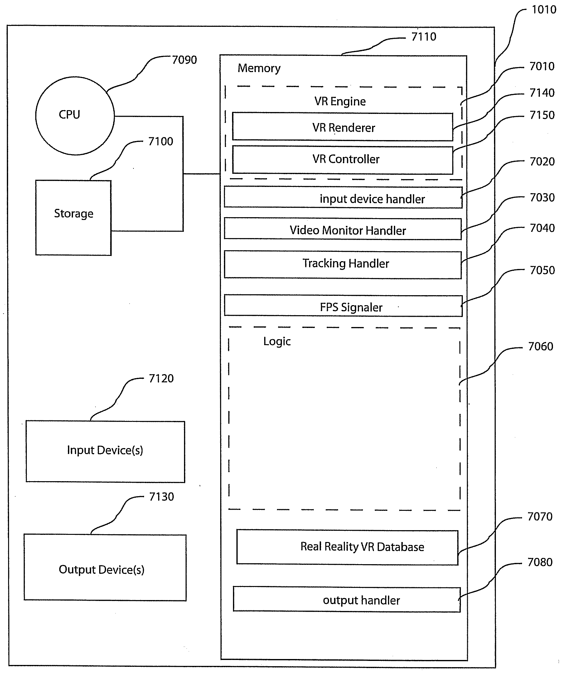
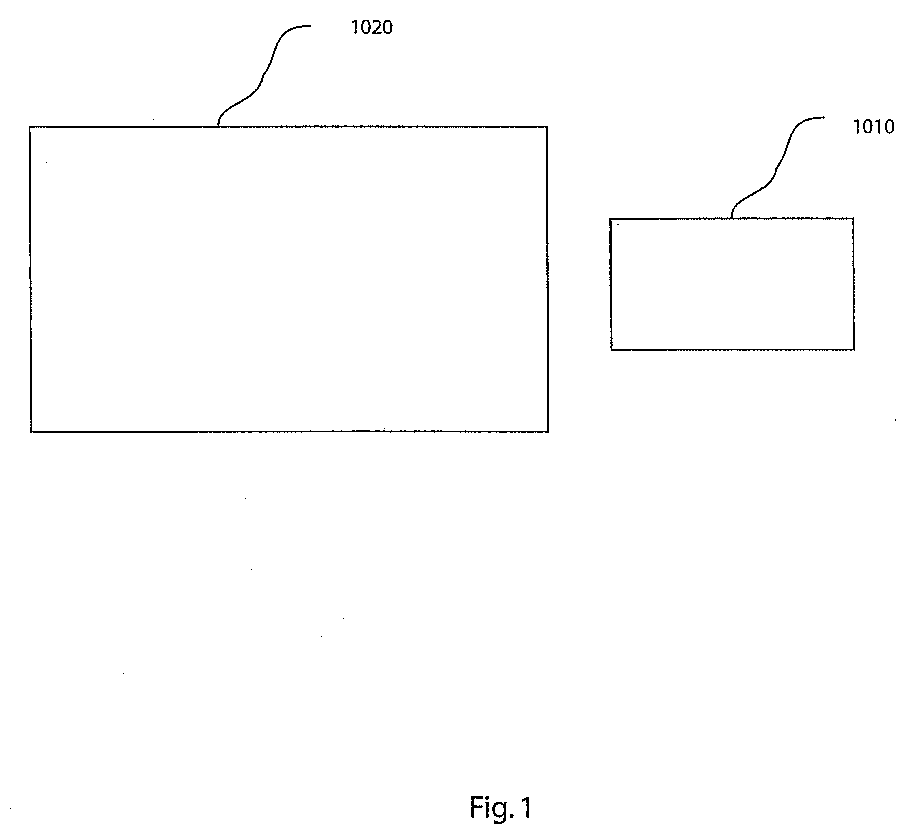
[0026]Turning now to the drawings in greater detail, it will be seen that in FIG. 1 there is an exemplary topology comprising two portions; a known environment 1020, and a system 1010. It is readily appreciated that this topology can be made more modularized. In this exemplary embodiment, the known environment 1020 is a room of a solid, uniform color. It will appreciated that the known environment 1020 is not limited to a solid uniform color room, rather other methods for removing a known environment from video are known and may be applicable.

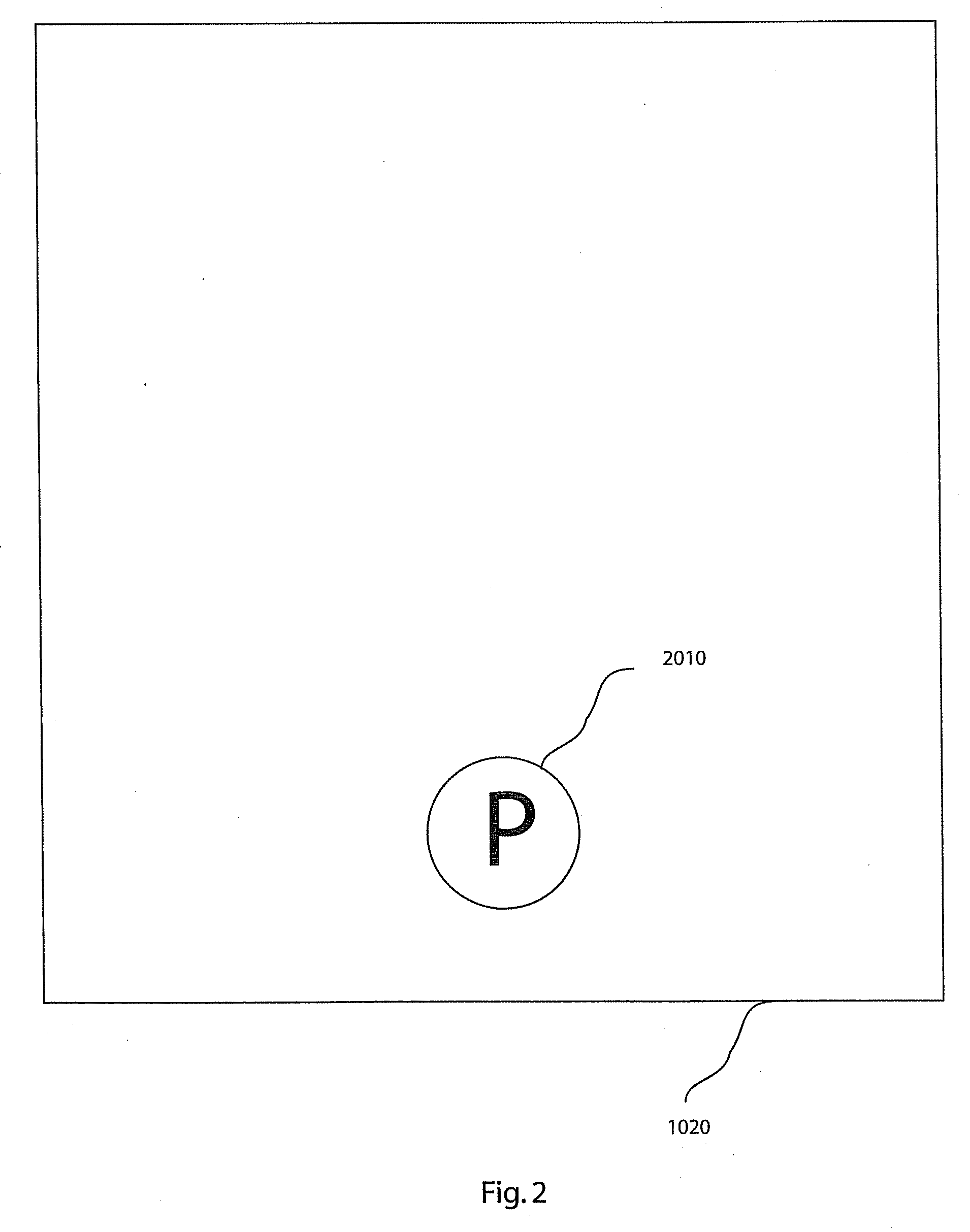
[0027]Turning also to FIGS. 2-5, there are examples shown of any number of objects 3010 (FIG. 3) and / or users (or people) 2010 to be placed in the known environment 1020. A user 2010 (FIG. 5) is described as having a head 5010, a body 5020, and optionally at least one device 5030, which can manipulate the system 1010 by generating an input. One input device 5030 may be as simple as a joystick, but is not limited to such as such input devices ar...


PUM


Abstract

A method and system for virtual reality imaging is presented. The method includes placing a user in a known environment; acquiring a video image from a perspective such that a field of view of the video camera simulates the user's line of sight; tracking the user's location, rotation and line of sight; filtering the video image to remove video data associated with the known environment without effecting video data associated with the user; overlaying the video image after filtering onto a virtual image with respect to the user's location to generate a composite image; and displaying the composite image in real time at a head mounted display. The system includes a head mounted display; a video camera disposed at the head mounted display such that a field of view of the video camera simulates a line of sight of a user when wearing the head mounted display, wherein a video image is obtained for the field of view; a tracking device configured to track the location, rotation, and line of sight of a user; and a processor configured to filter the video image to remove video data associated with a known environment without effecting video data associated with the user and to overlay the video image after it is filtered onto a virtual image with respect to the user's location to generate a composite image which is displayed by the head mounted display in real time.

Description

CROSS REFERENCE TO RELATED APPLICATIONS[0001]This application is a continuation application of U.S. patent application Ser. No. 11 / 462,839, filed Aug. 7, 2006, entitled A SYSTEM AND METHOD OF ENHANCED VIRTUAL REALITY and which is incorporated herein by reference in its entirety.BACKGROUND OF THE INVENTION[0002]1. Field of the Invention[0003]This invention relates to virtual reality, and particularly to a dynamically enhanced virtual reality system and method.[0004]2. Description of Background[0005]Before our invention, users of virtual reality have had difficulty in becoming fully immersed in the virtual space. This has been due to a lack of self, i.e., grounding themselves in the virtual world, which can result in a lack of belief of the virtual experience to disorientation and nausea.[0006]Presently, when a user enters a virtual reality or world, their notion of self is supplied by having a perspective themselves in the virtual reality, i.e., a feeling that they are looking throug...

Claims


Application Information

Patent Timeline
Patent Type & Authority Applications(United States)
IPC IPC(8): G09G5/00
CPCA63F13/10A63F2300/1012A63F2300/1093A63F2300/8082G06T7/0042G06T7/2033G06T19/006G06T2207/10016G06T2207/30196G06T2207/30241A63F13/52G06T7/246G06T7/73A63F13/213
Inventor HAILPERN, JOSHUA M.MALKIN, PETER K.
Owner INT BUSINESS MASCH CORP
Why Eureka
Try Eureka