Projection screen

Inactive Publication Date: 2008-10-09
YANGXIN TECH SUZHOU
View PDF8 Cites 0 Cited by
  • Summary
  • Abstract
  • Description
  • Claims
  • Application Information

AI Technical Summary

Benefits of technology

[0009]Accordingly, the present invention is directed to providing a projection screen, in which the

Problems solved by technology

On one hand, different projectors has different requirements on the screen, and a match problem between the two exists; on the other hand, as the projection circumstances has different lights, the requirements for the absorbency or reflectivity of screen on light are different.
Therefore, the screen of the electric projection screen of the above structure can merely adopt a single material, thereby being not capable of meeting the requirements for various materials corresponding to various projection requirements in actual practice.
However, some disadvantages still exist in the two methods of changing screens in the above structure.
For the former method, the screen and the casing are required to integrally rotate around the medial axis of the screen, a rotating space of at least a half of the casing length is required

Method used


Image

  • Projection screen
  • Projection screen
  • Projection screen

Examples


first embodiment

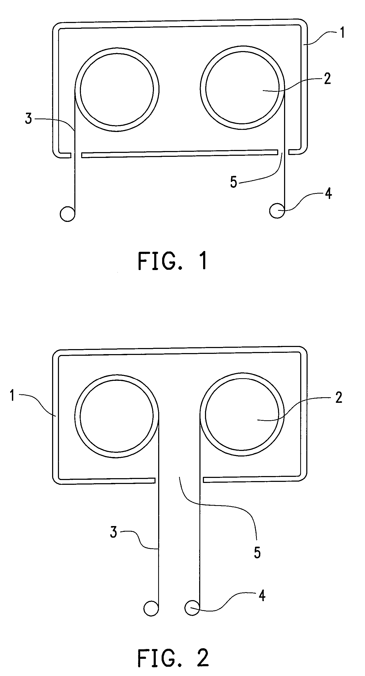
[0026]Referring to FIG. 1, a projection screen according to the present invention includes a casing 1, two shafts 2 disposed inside the casing, two screens 3 respectively wound on each of the shafts 2, and two driving devices respectively disposed in each of the shafts 2, for example, coaxial electric machines (not shown). Each of the screens 3 respectively has a stay tube 4 disposed at the bottom thereof, which is fixed on the screen 3. Each of the shafts 2 is laterally disposed inside the casing 1 in parallel. At the bottom of the casing 1, two parallel arranged openings are corresponding to the two screens 3, respectively. As the connection of the shafts 2 and the casing 1 and the connecting structure of the coaxial electric machines (not shown) and the shafts 2 can adopt the current technique and are not shown in the accompanied drawings. In operation, the screens 3 wound on the shafts 2 are different materials, that is to say, the screens have different microstructures, and thu...

third embodiment

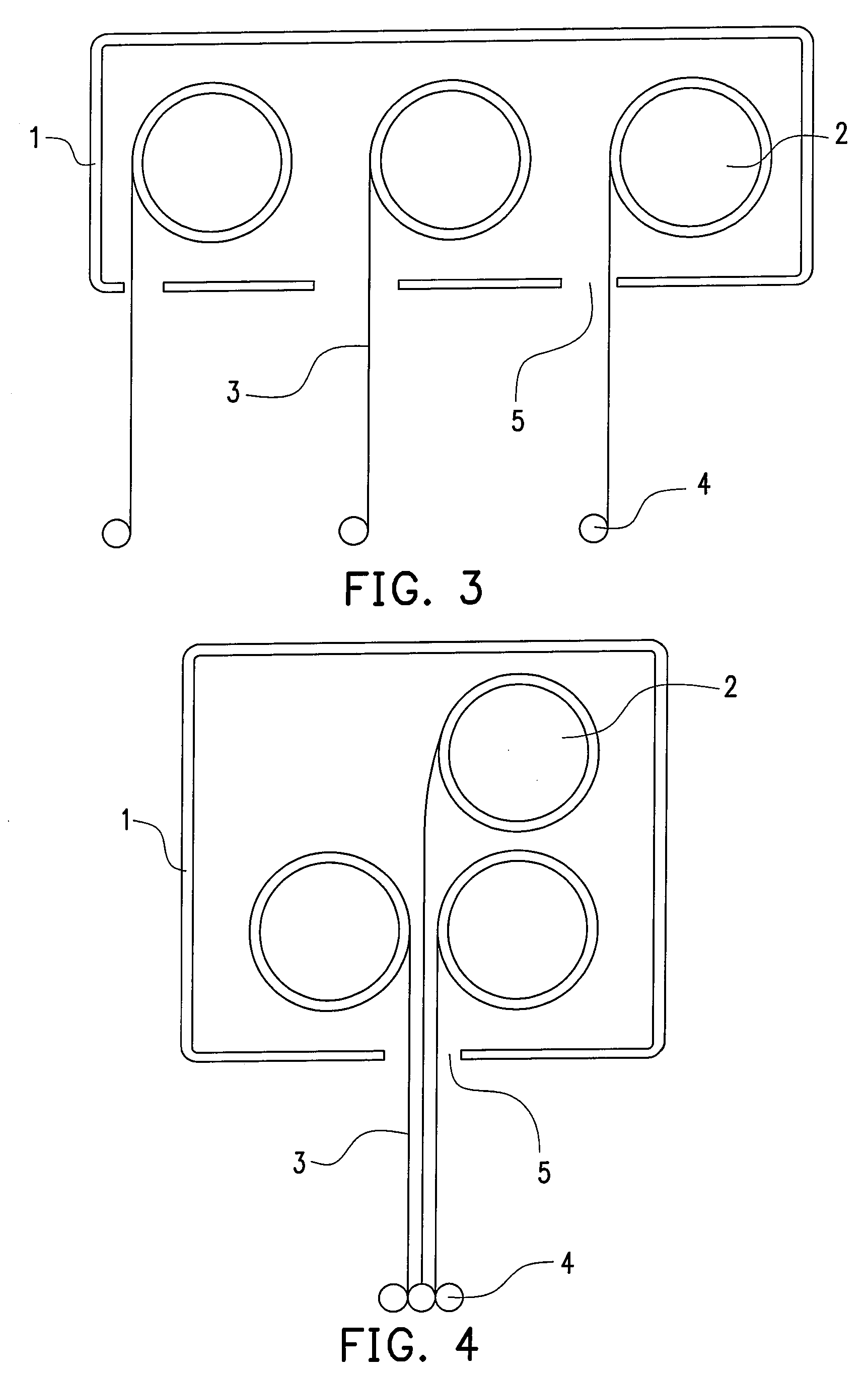
[0028]Referring to FIG. 3, a projection screen according to the present invention includes a casing 1, three shafts 2 disposed inside the casing 1, screens 3 respectively wound on each of the shafts 2, stay tubes 4 correspondingly disposed at the bottom of each of the screens 3 for fixing, and coaxial electric machine driving devices (not shown) disposed on each of the shafts 2, in which the three shafts 2 are laterally arranged inside the casing 1 in parallel, the positions of the three screens are, for example, on the lift side of the corresponding shafts 2, and the casing 1 has an opening 5 disposed corresponding to the position of each of the screens 3 at the bottom thereof.

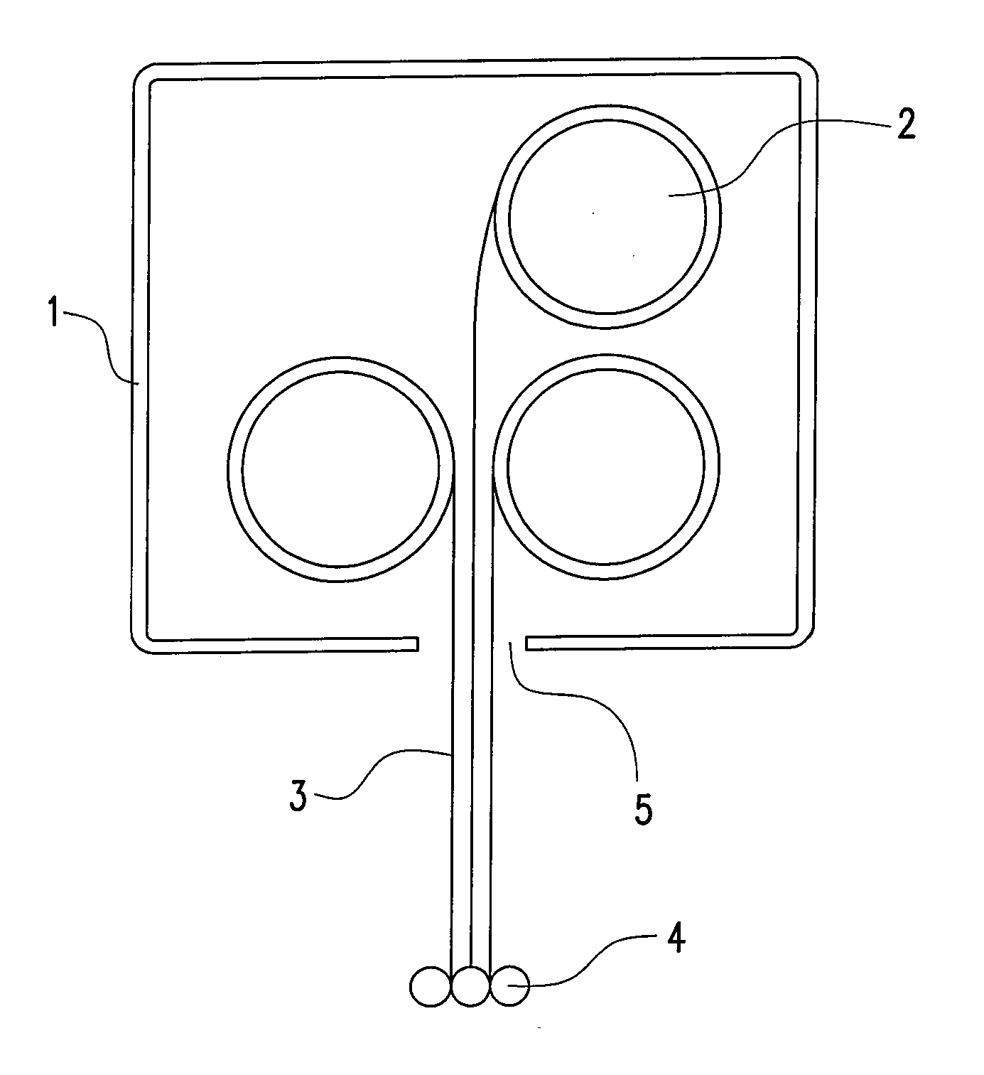
[0029]Referring to FIG. 4, as for a projection screen according to a fourth embodiment of the present invention, the structure thereof is similar to that of the third embodiment, and the difference lies in that the three shafts 2 are longitudinally arranged in a casing 1 in parallel in two rows, the casing 1 ...


PUM


Abstract

A projection screen is provided, which includes a casing having an opening disposed at the bottom thereof. The casing at least has two shafts, two screens, two stay tubes, and two driving devices disposed therein. Each of the shafts has a screen wound thereon, each screen correspondingly has a stay tube disposed at the bottom thereof, and each driving device drives a shaft. The shafts are disposed inside the casing and a screen of one material is wound on each shaft, thus the match between the projection screen and various projectors is realized by the alternation of the screens to adapt to various projection circumstances and contents, so as to obtain a better optimal projection effect.

Description

CROSS-REFERENCE TO RELATED APPLICATION[0001]This application claims the priority benefit of China application serial no. 200720036320.8, filed on Apr. 6, 2007. The entirety of the above-mentioned patent application is hereby incorporated by reference herein and made a part of this specification.BACKGROUND OF THE INVENTION[0002]1. Field of the Invention[0003]The present invention relates to a projection screen. More particularly, the present invention relates to a projection screen for a projector.[0004]2. Description of Related Art[0005]Projection devices are used to project images on a projection screen for amplifying and displaying images for presentation, propaganda, and teaching. The screen of the projection screen can be made of various materials with different properties. On one hand, different projectors has different requirements on the screen, and a match problem between the two exists; on the other hand, as the projection circumstances has different lights, the requirement...

Claims


Application Information

Patent Timeline
IPC IPC(8): H04N5/64
CPCG03B21/56
Inventor LEE, CHUN-TANG
Owner YANGXIN TECH SUZHOU
Why Eureka
Try Eureka