Image fusion method for dome screen system, and image fusion device thereof

A technology of image fusion and dome screen, which is applied in image enhancement, image analysis, image data processing and other directions, and can solve problems such as disappearing fusion bands

Inactive Publication Date: 2018-07-10
深圳市艺博堂文化科技集团有限公司
View PDF7 Cites 10 Cited by
  • Summary
  • Abstract
  • Description
  • Claims
  • Application Information

AI Technical Summary

Problems solved by technology

[0007] The technical problem mainly solved by the present invention is how to improve ...

Method used


Image

  • Image fusion method for dome screen system, and image fusion device thereof
  • Image fusion method for dome screen system, and image fusion device thereof
  • Image fusion method for dome screen system, and image fusion device thereof

Examples


Embodiment 1

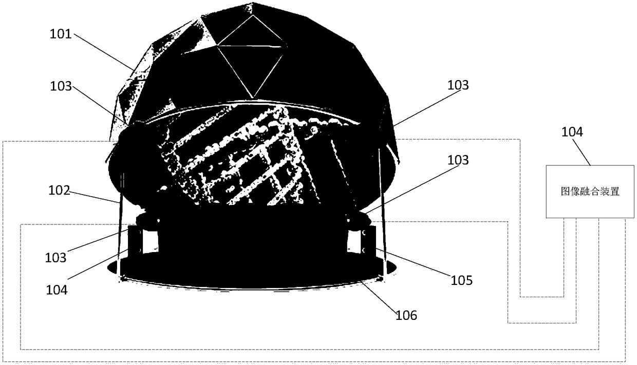
[0020] Embodiment 1. A ball screen system, such as figure 1 shown.

[0021] In this embodiment, the dome screen system includes a dome screen body 101 , a screen body support frame 102 , a projector 103 , an image fusion device 104 , an audio system 105 , and a seat 106 . The spherical screen body 101 is in the shape of a hemisphere or a spherical crown, and has a spherical screen for projection inside. The diameter of the spherical screen body 101 can be determined according to the actual application site, and is not limited here. The curtain body support frame 102 is used to carry the spherical curtain body 101, so that a chamber for people to enter and exit is formed under the spherical curtain body 101. There are six projectors 103 (two of which are not marked in the figure), and these projectors are evenly distributed on the annular edge of the spherical curtain body 101, and are used to form a three-dimensional projection picture on the spherical curtain of the spherica...

Embodiment 2

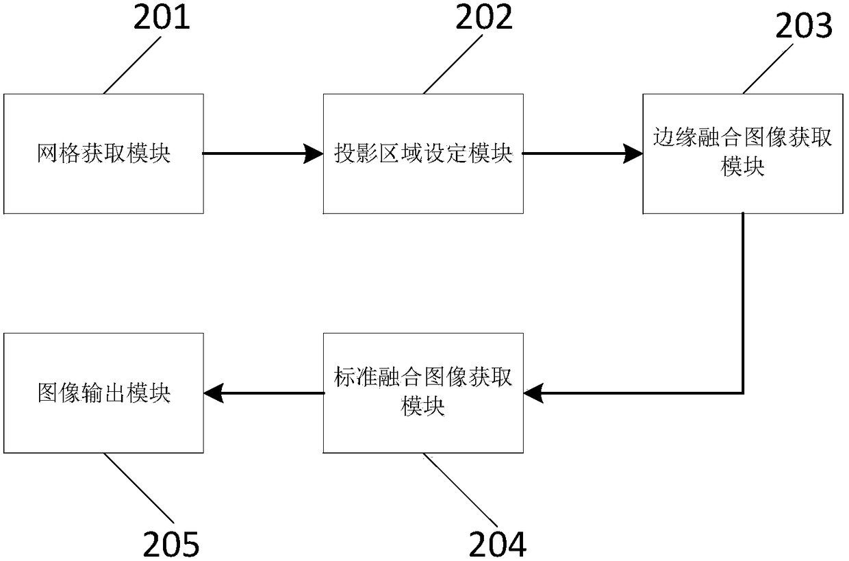
[0024] Embodiment 2. An image fusion device for a ball screen system, such as figure 2 shown.

[0025] In this embodiment, the image fusion device 104 includes a grid acquisition module 201 , a projection area setting module 202 , an edge fusion image acquisition module 203 , a standard fusion image acquisition module 204 and an image output module 205 .

[0026] The grid acquisition module 201 is used to acquire the grid model of the spherical curtain body, and the structure of the grid model is visible Figure 4, the grid model is made up of a ring column matrix and a pole matrix (the ring column matrix includes a ring column matrix unit, and these ring column matrix units are distributed in a circular shape according to the spherical surface of the spherical curtain body 101 and form a circle except the spherical cap area Ring area; the pole matrix includes pole matrix units one by one, and these pole matrix units are distributed in a circle around the pole positions on t...

Embodiment 3

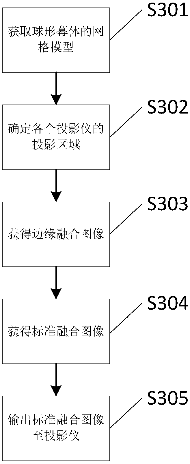
[0033] Embodiment 3. An image fusion method for a ball screen system, such as image 3 shown.

[0034] S301. Acquire a mesh model of a spherical curtain.

[0035] See figure 1 and figure 2 , the user outputs relevant parameters (such as diameter, inclination, number of projectors, etc.) grid model see Figure 4 , see Embodiment 2 for the specific description of the grid model.

[0036] S302. Determine the projection area of ​​each projector.

[0037] The projection area setting module 202 determines the annular projection area 401 and the pole projection area 402 corresponding to the projector 103 according to the grid model obtained in step S301, see Figure 4 . Utilize the projector 103 to project the spherical screen body 101, ensure that the overall projection area of ​​the projector 103 covers the spherical screen body 101, determine the edge matrix unit between each annular projection area in the overlapping projection area of ​​each two projectors, and The edge...


PUM


Abstract

The invention relates to an image fusion method for a dome screen system. The image fusion method for a dome screen system is characterized by determining the projection area of each projector by means of a mesh model of the dome screen body so as to enable each projector to have adjustability for the projection position; performing edge fusion on each projection area by means of polar coordinatesgeometrical correction processing, so as to enable the projection area image at different position and in different size to achieve the effect of accurate splicing; and respectively performing colorcalibration of the projectors and fusion band blanking operation of projection images by means of unified color processing and light leakage compensation processing, thus effectively avoiding color variation and luminance variation between each edge fusion image. By means of the steps provided by the image fusion method for a dome screen system, the stereo projection image on the dome screen bodycan achieve the display effect of complete frames, unified color and suitable luminance, and comfortable and perfect film watching experience can be brought to spectators. The image fusion device employing the image fusion method for a dome screen system can generate a standard fusion image with better display effect, and the dome screen system employing the image fusion method can have excellentprojection effect and can improve the film watching experience of spectators.

Description

technical field [0001] The invention relates to the technical field of screen projection display, in particular to an image fusion method and an image fusion device for a ball screen system. Background technique [0002] The dome screen system is a platform for displaying images or videos using internal projection technology. This system breaks the previous limitation that projected images can only be plane regular graphics. The screen of the internal projection screen is a spherical rear projection screen placed on the dome screen. The internal projector projects the image onto almost the entire spherical screen, and the audience can have a three-dimensional surround viewing experience. [0003] The shape of the sphere in the inner projection screen is very suitable for the appearance of the cosmic celestial body, and it has great advantages in expressing the cosmic celestial body. As long as we display the images describing the celestial bodies such as planets, satellites,...

Claims


Application Information

Patent Timeline
IPC IPC(8): G06T3/00G06T5/50G06T3/40
CPCG06T3/0012G06T3/4038G06T5/50G06T2207/20221
Inventor 郑洵
Owner 深圳市艺博堂文化科技集团有限公司
Why Eureka
Try Eureka