
Position-Independent Microphone System

a position-independent, microphone technology, applied in the field of acoustics, can solve the problems of not recovering the loss of attenuation of farfield sources, unable to achieve sufficient gain,

Active Publication Date: 2008-10-09
MH ACOUSTICS
View PDF9 Cites 44 Cited by
  • Summary
  • Abstract
  • Description
  • Claims
  • Application Information

AI Technical Summary

Problems solved by technology

However, for highly noise-contaminated environments, the achievable gain might not be sufficient.
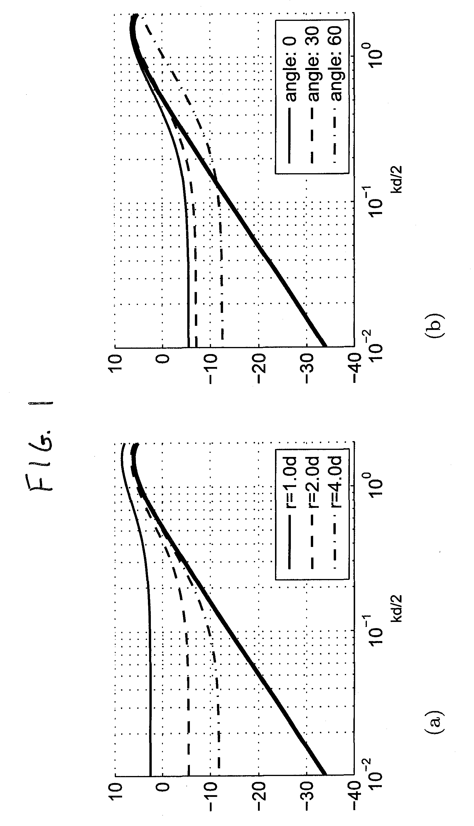
While this method provides a large improvement over conventional close-talking microphone arrays, it does not allow recovering the loss in attenuation of farfield sources due to orientation of the microphone array.

Method used


Image

  • Position-Independent Microphone System
  • Position-Independent Microphone System
  • Position-Independent Microphone System

Examples


Embodiment Construction

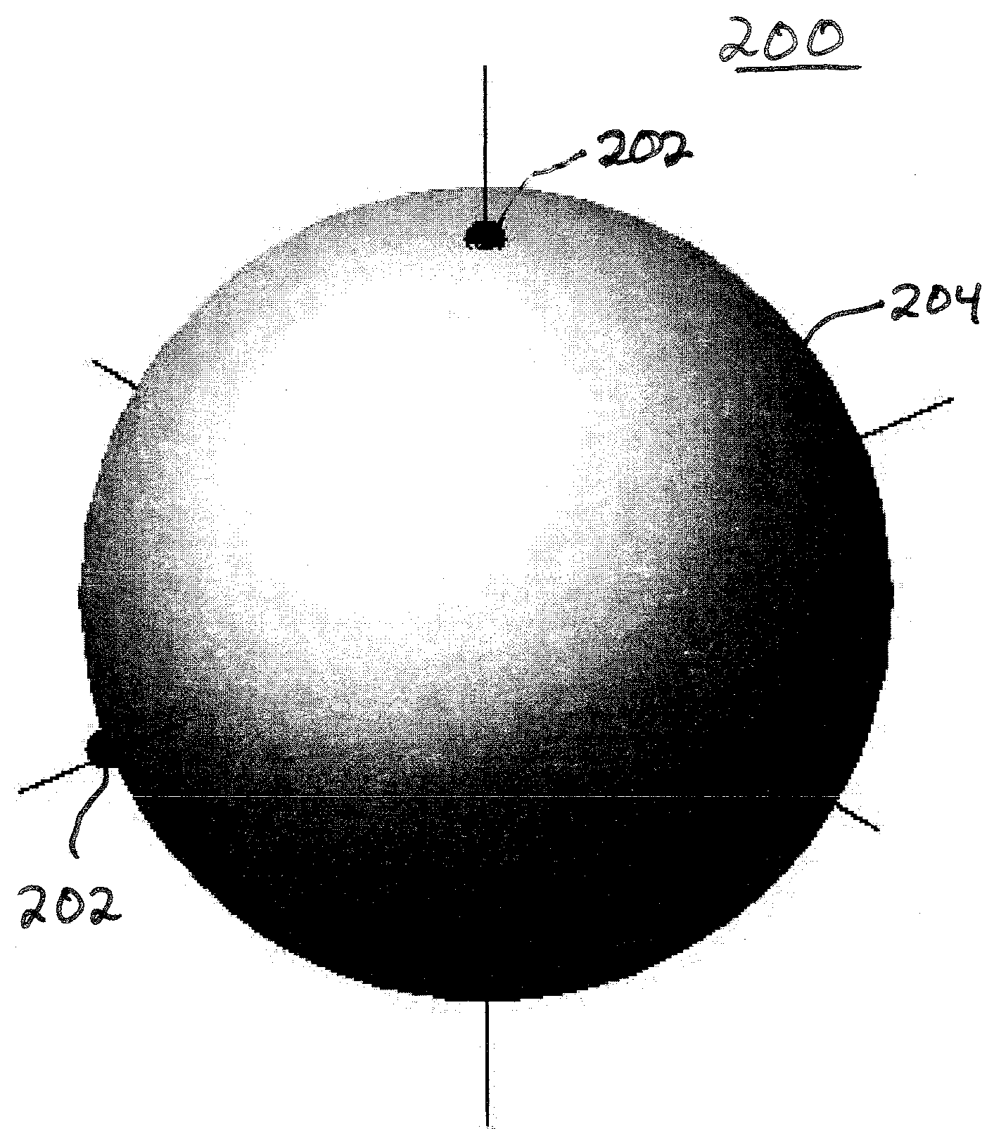
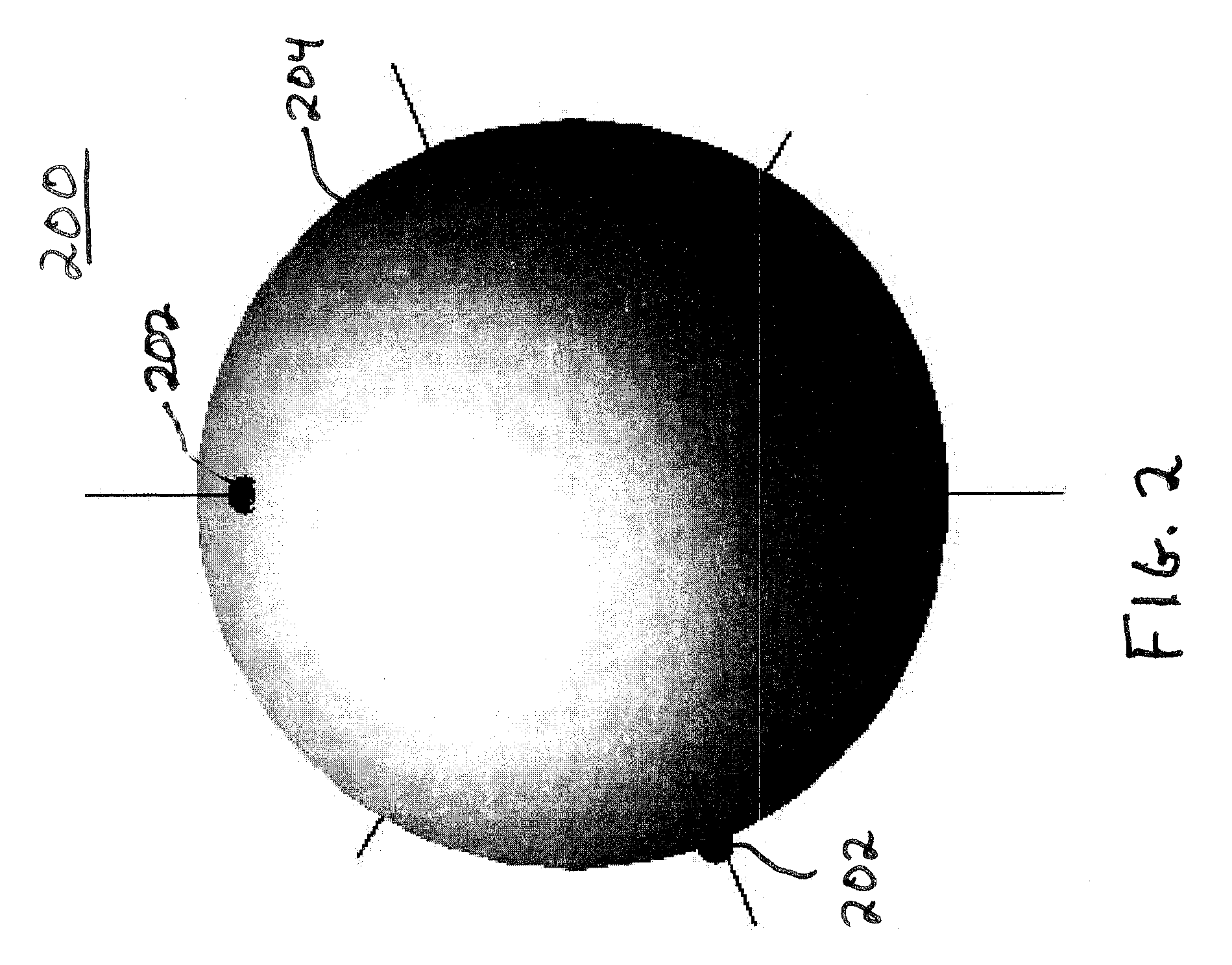
[0022]According to certain embodiments of the present invention, a microphone array consisting of a plurality of audio sensors (e.g., microphones) generates a plurality of (time-varying) audio signals, one from each audio sensor in the array. The audio signals are then decomposed (e.g., by a digital signal processor or an analog multiplication network) into a (time-varying) series expansion involving discretely sampled (e.g., spherical) harmonics, where each term in the series expansion corresponds to the (time-varying) coefficient for a different three-dimensional eigenbeam.

[0023]Note that the number and location of microphones in the array determine the order of the harmonic expansion, which in turn determines the number and types of eigenbeams in the decomposition. For example, as described in more detail below, an array having four appropriately located microphones supports a discrete first-order harmonic expansion involving one zero-order eigenbeam and three first-order eigenbe...


PUM


Abstract

An audio system generates position-independent auditory scenes using harmonic expansions based on the audio signals generated by a microphone array. In one embodiment, a plurality of audio sensors are mounted on the surface of a sphere. The number and location of the audio sensors on the sphere are designed to enable the audio signals generated by those sensors to be decomposed into a set of eigenbeam outputs. Compensation data corresponding to at least one of the estimated distance and the estimated orientation of the sound source relative to the array are generated from eigenbeam outputs and used to generate an auditory scene. Compensation based on estimated orientation involves steering a beam formed from the eigenbeam outputs in the estimated direction of the sound source to increase direction independence, while compensation based on estimated distance involves frequency compensation of the steered beam to increase distance independence.

Description

CROSS-REFERENCE TO RELATED APPLICATIONS[0001]This application claims the benefit of the filing date of U.S. provisional application No. 60 / 659,787, filed on Mar. 9, 2005 as attorney docket no. 1053.005PROV, the teachings of which are incorporated herein by reference.[0002]In addition, this application is a continuation-in-part of U.S. patent application Ser. No. 10 / 500,938, filed on Jul. 8, 2004 as attorney docket no. 1053.001B, which is a 371 of PCT / US03 / 00741, filed on Jan. 10, 2003 as attorney docket no. 1053.001PCT, which itself claims the benefit of the filing date of U.S. provisional application No. 60 / 347,656, filed on Jan. 11, 2002 as attorney docket no. 1053.001PROV and U.S. patent application Ser. No. 10 / 315,502, filed on Dec. 10, 2002 as attorney docket no. 1053.001, the teachings of all of which are incorporated herein by reference.BACKGROUND OF THE INVENTION[0003]1. Field of the Invention[0004]The present invention relates to acoustics, and, in particular, to microphone...

Claims


Application Information

Patent Timeline
Patent Type & Authority Applications(United States)
IPC IPC(8): H04R3/00
CPCH04R3/005H04S3/002
Inventor ELKO, GARY W.MEYER, JENS M.
Owner MH ACOUSTICS
Learn More