System and Method for Providing Mobile Range Sensing

a mobile range and sensing technology, applied in image analysis, image enhancement, instruments, etc., can solve the problems of requiring high power, affecting the accuracy of the image, and using images from a moving platform

Inactive Publication Date: 2008-10-09
SRI INTERNATIONAL
View PDF10 Cites 26 Cited by
  • Summary
  • Abstract
  • Description
  • Claims
  • Application Information

AI Technical Summary

Problems solved by technology

A persistent issue in the sensing system is the need to determine the structure of a scene, including objects seen at long distances using a mobile platform.
The difficulty with using images from a moving platform is knowing the precise relationship (position and direction) between the cameras that acquired the images.
A conventional approach is to use a laser range finder or LADAR, but these ranges require high power, and LADAR is emissive.
So, the scene structure typically recovered from LADAR sensing has power / speed / resolution limitations at the ranges of interest (hundreds of meters to a kilometer or more).
Accurate range estimates for objects that are a kilometer away, however, requires a 10 m baseline, which is impractical for a mobile, fixed-baseline system.
So, scene structure recovered from conventional stereo vision systems have a fixed baseline that limits range and / or mobility of the stereo system.

Method used


Image

  • System and Method for Providing Mobile Range Sensing
  • System and Method for Providing Mobile Range Sensing
  • System and Method for Providing Mobile Range Sensing

Examples


Embodiment Construction

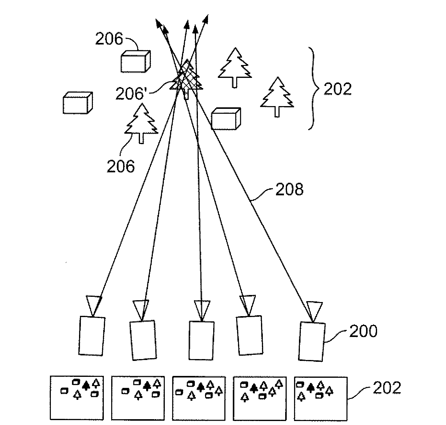
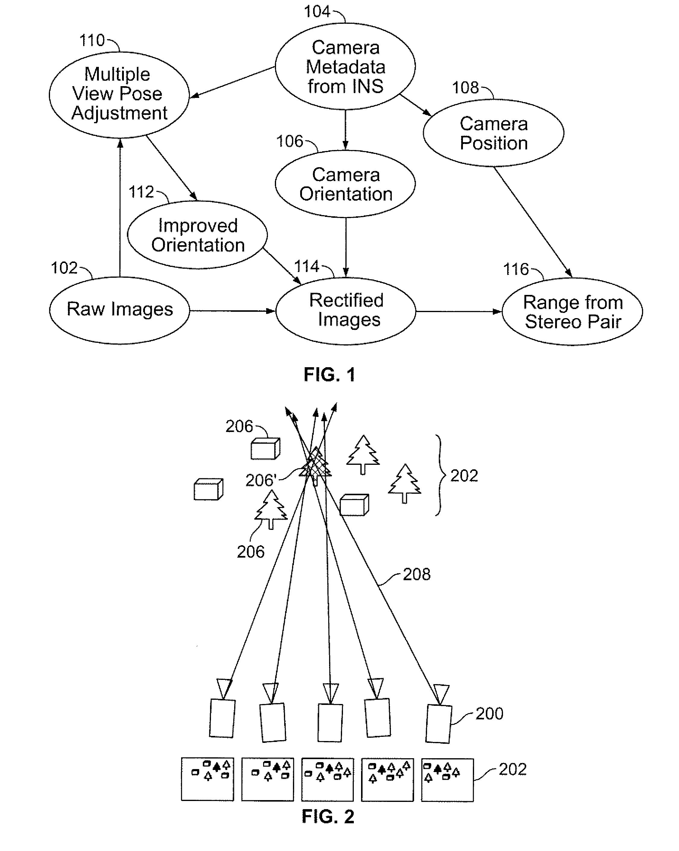
[0018]The basic scenario in the present invention is that images of essentially the same scene are captured from multiple viewpoints. The images are captured preferably due to one camera mounted on a moving platform or alternatively due to multiple cameras mounted on the moving platform that are moving through the scene. So, if the relative camera positions are known, the present invention proposes to rectify the images (correct them for differing camera orientations) prior to computing the stereo disparity (through image-matching techniques) to determine the range to objects in the scene. Referring to FIG. 1, there is shown a flow diagram of the procedure of visual means of the sensing system in accordance with an embodiment of the present invention. A series of raw images are captured at step 102 from the camera (not shown) mounted on a moving platform. Note that these images are captured at different camera locations or at different camera separations relative to the first camera...


PUM


Abstract

The present invention provides an improved system and method for estimating range of the objects in the images from various distances. The method comprises receiving a set of images of the scene having multiple objects from at least one camera in motion. Due to the motion of the camera, each of the images are obtained at different camera locations Then an object visible in multiple images is selected. Data related to approximate camera positions and orientations and the images of the visible object are used to estimate the location of the object relative to a reference coordinate system. Based on the computed data, a projected location of the visible object is computed and the orientation angle of the camera for each image is refined. Additionally, pairs of cameras with various locations can then be chosen to obtain dense stereo for regions of the image at various ranges. The process is further structured so that as new images arrive, they are incorporated into the pose adjustment so that the dense stereo results can. be updated.

Description

CROSS-REFERENCE TO RELATED APPLICATIONS[0001]This application claims the benefit of U.S. Provisional Patent Application No. 60 / 847,000 filed Sep. 25, 2006, the entire disclosure of which is incorporated herein by reference.GOVERNMENT RIGHTS IN THIS INVENTION[0002]This invention was made with U.S. government support under contract number DAAD19-01-2-0012. The U.S. government has certain rights in this invention.FIELD OF THE INVENTION[0003]The invention relates generally to a visual means for a mobile sensing system for refining camera poses used to acquire multiple views of a scene. More specifically, the invention relates to an improved system and method for estimating range including objects in the images from various distances.BACKGROUND OF THE INVENTION[0004]A persistent issue in the sensing system is the need to determine the structure of a scene, including objects seen at long distances using a mobile platform. Scene structure recovered in the range of 50 m-1000 m is useful for...

Claims


Application Information

Patent Timeline
Patent Type & Authority Applications(United States)
IPC IPC(8): G06K9/00G06V10/147
CPCG06K9/209G06K2209/40G06T7/0077G06T7/2033G06T2207/10016G06T2207/30188G06T2207/30241G06T2207/30252G06T7/596G06T7/246G06V10/147G06V2201/12
Inventor FIELDS, JOHN RICHARDBERGEN, JAMES RUSSELLSALGIAN, GARBIS
Owner SRI INTERNATIONAL
Why Eureka
Try Eureka