Pluggable optical transceiver

Inactive Publication Date: 2008-10-09
SUMITOMO ELECTRIC IND LTD
View PDF6 Cites 34 Cited by
  • Summary
  • Abstract
  • Description
  • Claims
  • Application Information

AI Technical Summary

Benefits of technology

[0011]The present invention is to provide a pluggable optical transceiver with an innovative mechanism, by which the transceiver may be easily extra

Problems solved by technology

In such system, when transceivers around the target one receive the optical connector, it is often encountered that the bail of the target transceiver is hard to extract the targe

Method used


Image

  • Pluggable optical transceiver
  • Pluggable optical transceiver
  • Pluggable optical transceiver

Examples


Example

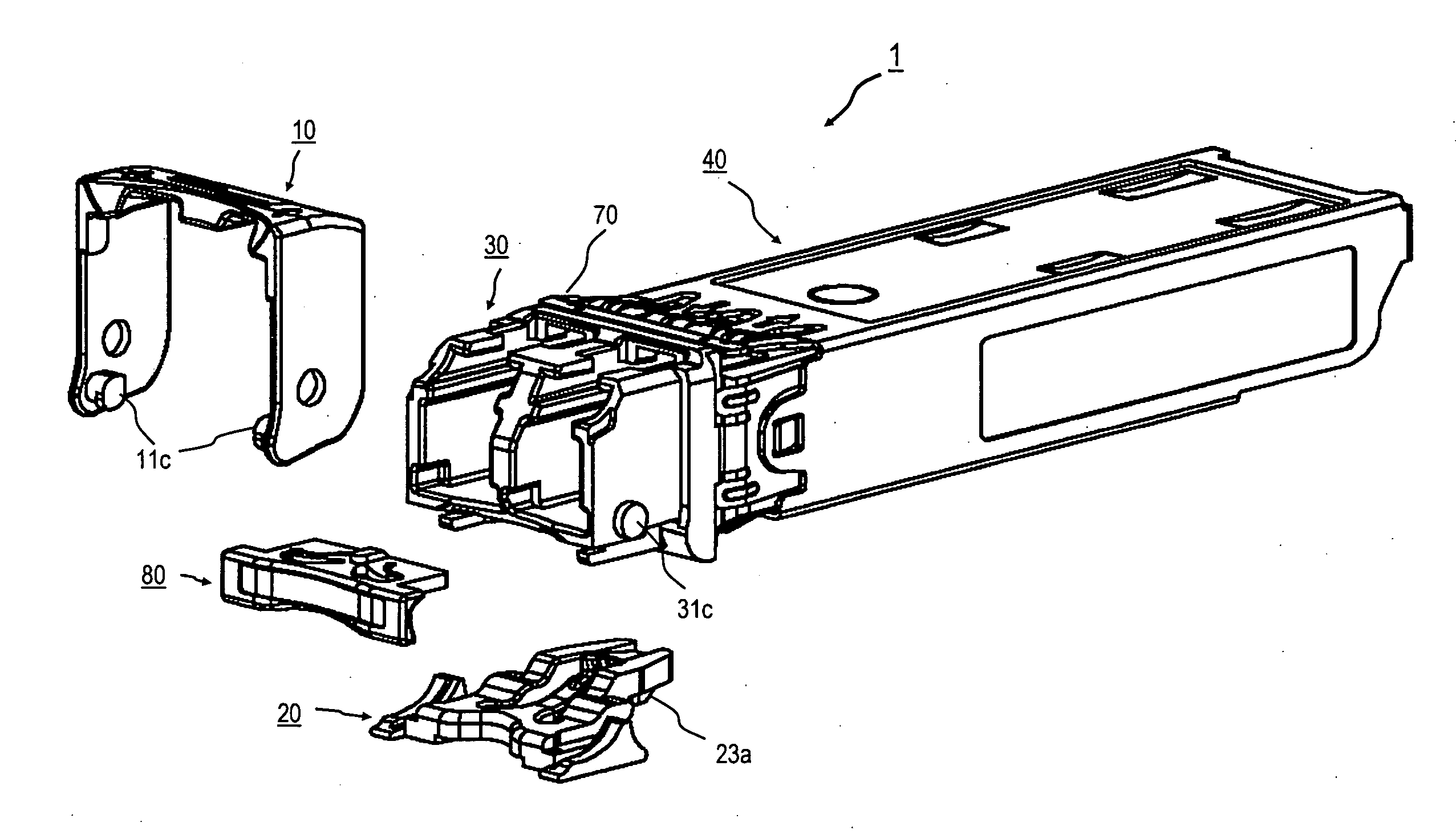
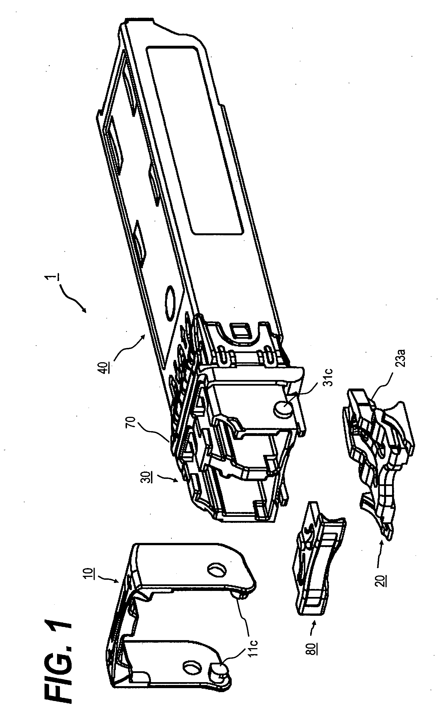
[0022]FIG. 1 is a perspective view of a pluggable optical transceiver (hereinafter called as a transceiver) according to an embodiment of the present invention. The transceiver 1 includes a bail 10, an actuator 20, an optical receptacle 30, a cover 40, a ground tab 70 and a release button 80. Here, the front side of the transceiver 1 is a side where the optical receptacle is installed, while the rear side is a side opposite thereto. Moreover, a side that is not illustrated in FIG. 1, that is, the optical receptacle 30 provides the actuator therein, is regarded as the lower side, while the other side, which is illustrated as an open side, is regarded as the upper side. The upper and lower sides above defined reflect the practical direction when the transceiver 1 is inserted in the cage.

[0023]The cage, which is installed on the host board, receivers the rear side of the transceiver 1 such that an electrical plug, which is hidden in FIG. 1, provided in the rear end of the transceiver 1...


PUM


Abstract

The present invention provides a new releasing mechanism form a cage on the host system for a pluggable optical transceiver. The transceiver includes an optical receptacle, an actuator with a hook that latches with the key hole of the cage, a bail attached so as to rotate in front of the receptacle and a release button. Rotating the bail or pushing the button will bring the seesaw motion of the actuator that disengages the hook with the keyhole and the transceiver is enabled to be extracted from the cage by picking the bail positioned in front of the receptacle.

Description

[0001]This application closely relates to pending applications Ser. No. 11 / 117,695, filed Apr. 29, 2005, entitled “Releasing mechanism of pluggable transceiver”, and Ser. No. 11 / 372,230, filed Mar. 8, 2006, entitled “RELEASING MECHANISM OF PLUGGABLE TRANSCEIVER FROM CAGE”, both of which are assigned to the same assignee of the present application, the entire contents of which are incorporated herein by references.BACKGROUND OF THE INVENTION[0002]1. Field of the Invention[0003]The present invention relates to a mechanism of an optical pluggable transceiver for latching with / releasing from a cage.[0004]2. Related Prior Art[0005]The so-called pluggable transceiver is inserted into the cage of the host system. The cage is a metal box with one end thereof opening for the outside. This cage is installed on the host system such that an electrical connector on the host system is set in the deep end of the cage, and the opened end is exposed in the face panel of the host system. Thus, the pl...

Claims


Application Information

Patent Timeline
IPC IPC(8): H04B10/04
CPCG02B6/3897G02B6/4246G02B6/4277G02B6/4292
Inventor YOSHIKAWA, SATOSHISASAKI, HIROKAZU
Owner SUMITOMO ELECTRIC IND LTD
Why Eureka
Try Eureka