Video blade laryngoscope

a laryngoscope and video technology, applied in the field of laryngoscopes, can solve the problems of delay in patient intubation, inability to intubate by direct visualization, and inability to use video laryngoscopes

Active Publication Date: 2008-10-09
KARL STORZ ENDOVISION INC
View PDF22 Cites 51 Cited by
  • Summary
  • Abstract
  • Description
  • Claims
  • Application Information

AI Technical Summary

Benefits of technology

[0016]In this manner, any sensitive electronics may be removed from the handle, for example, during the sterilization process so that they are not exposed to the relatively high temperatures encountered during the process.

Problems solved by technology

However, video laryngoscopes due to their specialized construction, traditionally do not allowed for intubation by direct visualization.
This disadvantageously leads to delay in intubation of the patient due at least in part to the fact that the physician has to change instruments.
While this configuration functions as a video laryngoscope, the lifter portion extends upward from the upper surface of the blade such that any direct visualization by a physician is virtually impossible.
Another problem that traditional video laryngoscopes face is the limited interface ability they have with monitors.
For example, a video laryngoscope typically is designed and can only be used with a single type of monitor, e.g. either an O.R. monitor or a P.C. This is disadvantageous as the physician may desire to switch monitors, for example, the laryngoscope may be attached to an O.R. monitor but the physician wants to connect the laryngoscope to a relatively small portable computer monitor as the patient is transported.
Yet another problem associated with video laryngoscopes is the fact that, many imaging chips are positioned in a cavity or enclosure at a distal end of the laryngoscope blade and are enclosed by a transparent window.
However, the window often becomes fogged during the procedure thereby limiting the ability of the physician to see clearly.

Method used


Image

  • Video blade laryngoscope
  • Video blade laryngoscope
  • Video blade laryngoscope

Examples


Embodiment Construction

[0030]Referring now to the drawings, wherein like reference numerals designate corresponding structure throughout the views.

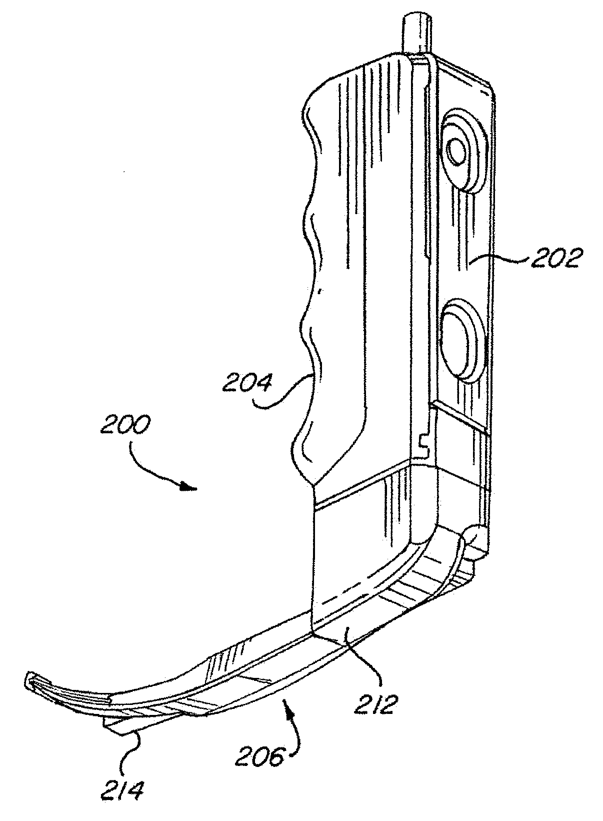
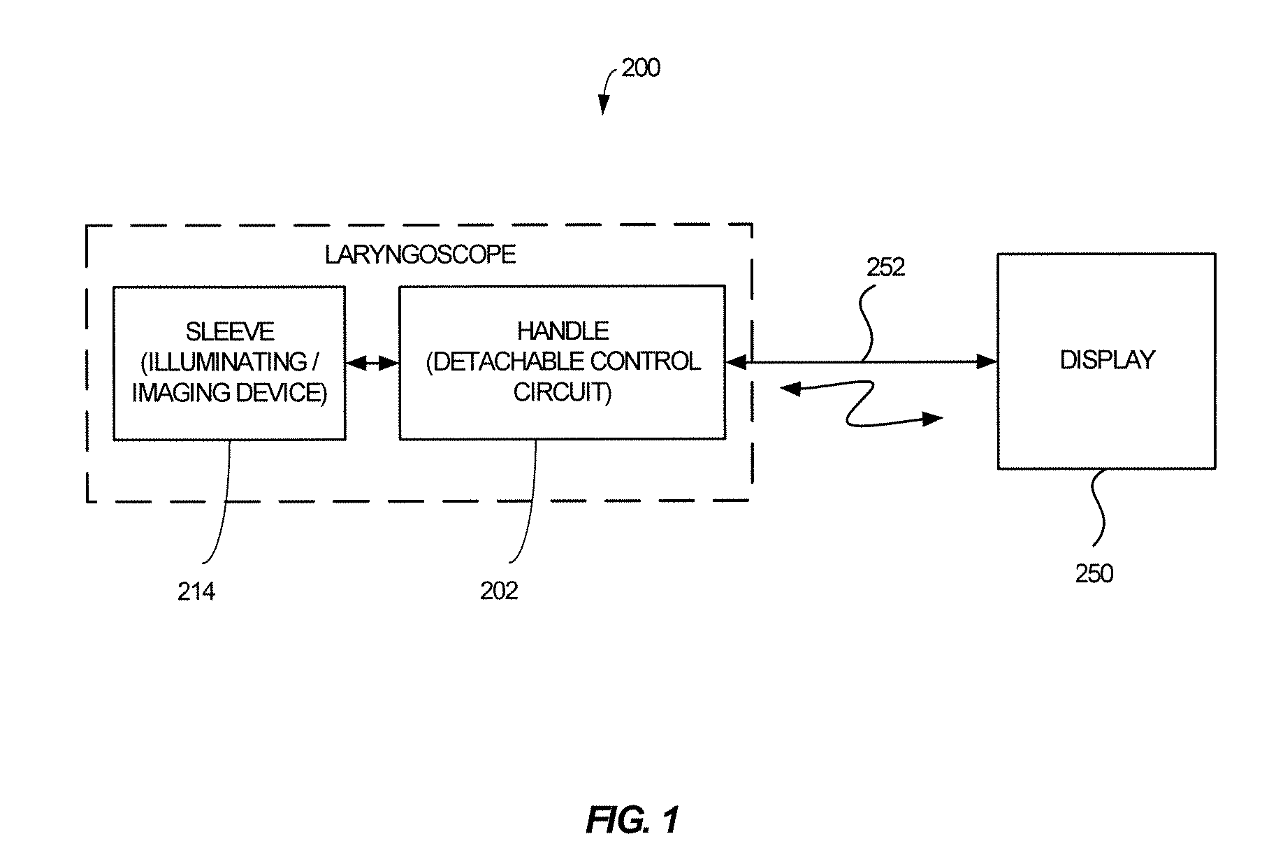
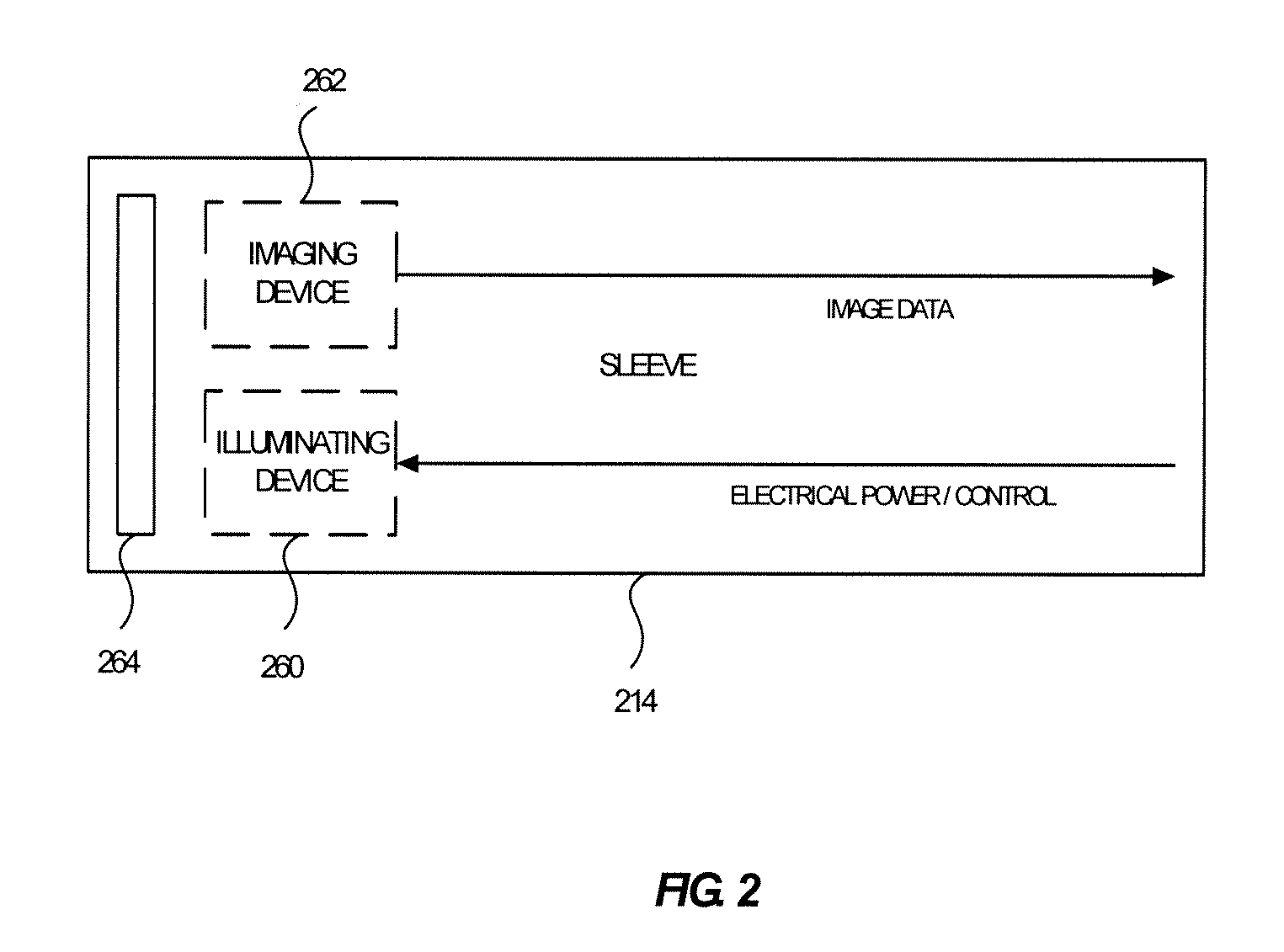
[0031]One advantageous embodiment of the present invention is variously illustrated in FIGS. 1-7 including laryngoscope 200. FIGS. 1 and 2 are block diagrams illustrating various functional arrangements of laryngoscope 200, while FIGS. 3-7 are various prospective views of an advantageous embodiment of the present invention.

[0032]Laryngoscope 200 generally comprises a control circuit 202, which is insertable into or detachably connectable to a handle 204 of the laryngoscope 200. In addition, a blade 206 is coupled to handle 204 and a sleeve 214 may be coupled to control circuit 202 for transmitting image data to the control circuit, which is in turn, transmitted to a display 250. FIG. 1 illustrates use of, for example, a cable 252 or use of a wireless coupling to display 250.

[0033]It is contemplated that cable 252 may provide electrical power to control circuit ...


PUM


Abstract

A laryngoscope including a control circuit that is detachably connectable to a handle, where the control circuit functions and is compatible with a wide variety of displays. The laryngoscope may optionally be used in either the video mode where the user views a display presenting image data of the area ahead of the blade, or the user may use the laryngoscope in the direct visualization where the user uses the laryngoscope in a traditional manner directly viewing the area ahead of the blade during the intubation procedure. When used in the video mode, an LED is positioned adjacent to a window enclosing the digital image sensor to defog the window.

Description

FIELD OF THE INVENTION[0001]The invention relates to a laryngoscope, and more particularly to a laryngoscope that may be used with many differing video monitors and that also may be used as either a video laryngoscope or as a direct visualization laryngoscope having a blade with a smooth upper surface so as not to interfere with direct visualization of a patient's trachea.BACKGROUND OF THE INVENTION[0002]A number of medical procedures require ventilation be provided to the patient, which may be provided through an endotracheal tube. This tube may be inserted into the trachea. It should be noted that when the tube is inserted, the patient is asleep hyperoxygenated and then paralyzed for the procedure, and therefore not breathing. As the ventilator is not yet in operation, the physician must work quickly to insert the endotracheal tube.[0003]With the advent of endoscopic equipment and small cameras, instrumentation can enable viewing of the cords and larynx on a video screen facilitat...

Claims


Application Information

Patent Timeline
Patent Type & Authority Applications(United States)
IPC IPC(8): A61B1/267
CPCA61B1/00105A61B1/05A61B1/051A61B1/127A61B1/267A61B1/0676A61B1/00066
Inventor BIRNKRANT, DASHIELLBARRY, JAMES P.
Owner KARL STORZ ENDOVISION INC
Why Eureka
Try Eureka