
Warning System and Method of Providing a Warning

a technology of a warning system and a warning device, which is applied in the direction of anti-theft devices, vehicle components, signalling/lighting devices, etc., can solve the problem of inconvenience for drivers

Inactive Publication Date: 2008-10-16
NISSAN MOTOR CO LTD
View PDF11 Cites 3 Cited by
  • Summary
  • Abstract
  • Description
  • Claims
  • Application Information

AI Technical Summary

Benefits of technology

The present invention provides a power position warning system for vehicles that detects the vehicle's power position and gear shift position, and alerts the driver when they are not in the correct position for safe driving. This system can detect when the driver is preparing to alight from the vehicle, and will output a warning indication until the power position and gear shift position are corrected. The power position warning indication can be visual or auditory, and may be continued until the driver has returned to the correct position or the engine has started. This system helps to prevent the inconvenience of having to repeat opening the door after having closed it, and ensures safe driving habits for the driver.

Problems solved by technology

Consequently, the driver has the inconvenience of then having to open the door again and carry out the required operation to return the power position to IGN-OFF.

Method used


Image

  • Warning System and Method of Providing a Warning
  • Warning System and Method of Providing a Warning
  • Warning System and Method of Providing a Warning

Examples


Embodiment Construction

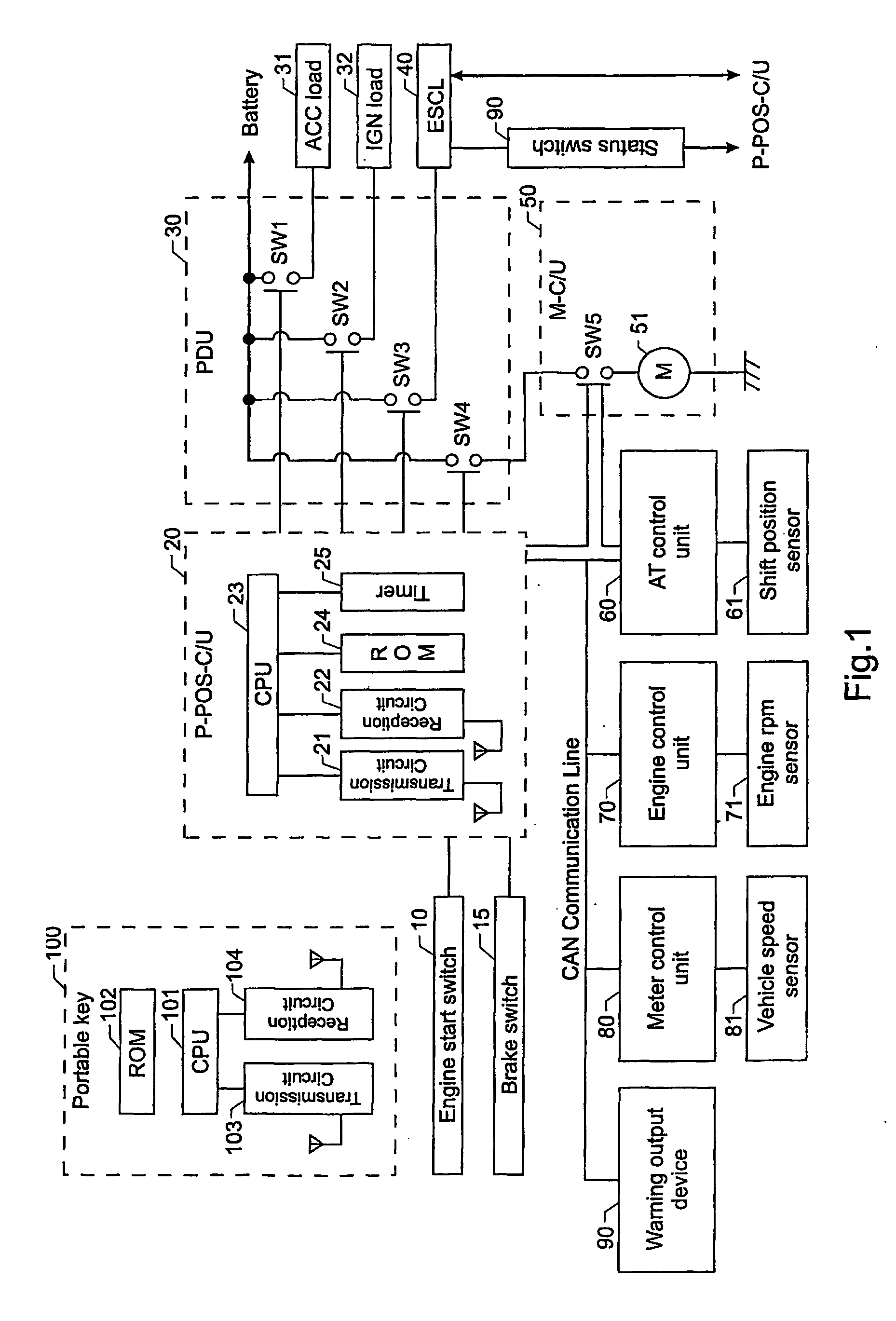
[0037]FIG. 1 shows an example of the configuration of the engine control device where the power position warning device of this invention may be applied. First of all, an explanation about the configuration of a first form of embodiment of this invention will be made with reference to FIG. 1.

[0038]An engine start switch 10 is a push-button type of switch (not shown), which is operated by the driver when starting the engine. If the switch 10 is pressed when the prescribed conditions are fulfilled, engine starting control commences. Moreover, the engine start switch 10 is used also when various power positions are moved to, such as stopping the engine during running. A brake switch 15 is made ON when the brake (not shown) is applied by a user activating or treading on a brake activator or pedal.

[0039]A Power Position Control Unit (hereinafter referred to as P-POS-C / U) 20 is provided with a transmission circuit 21, a reception circuit 22, a CPU 23, a ROM 24 and a timer 25. The transmis...


PUM


Abstract

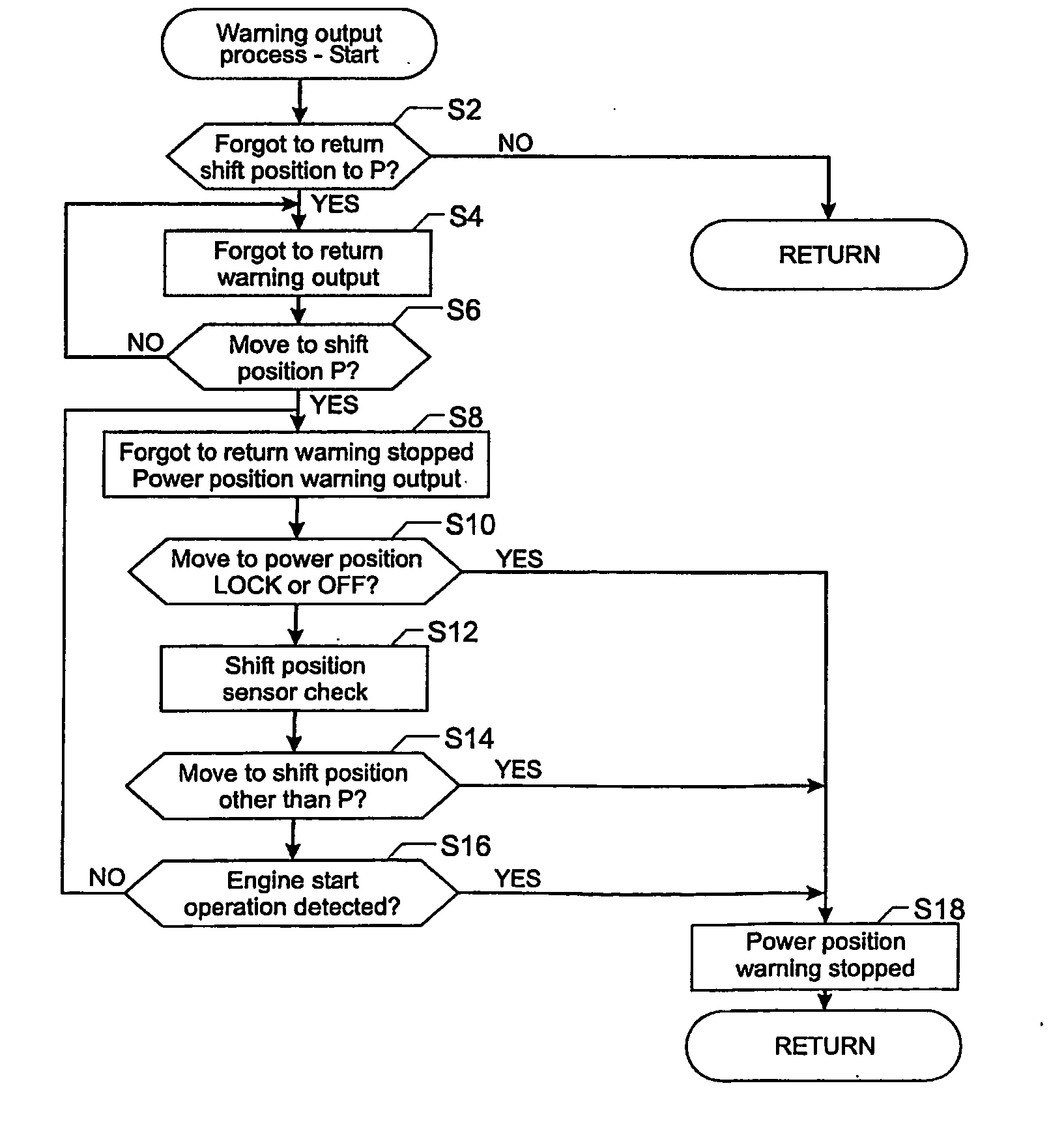
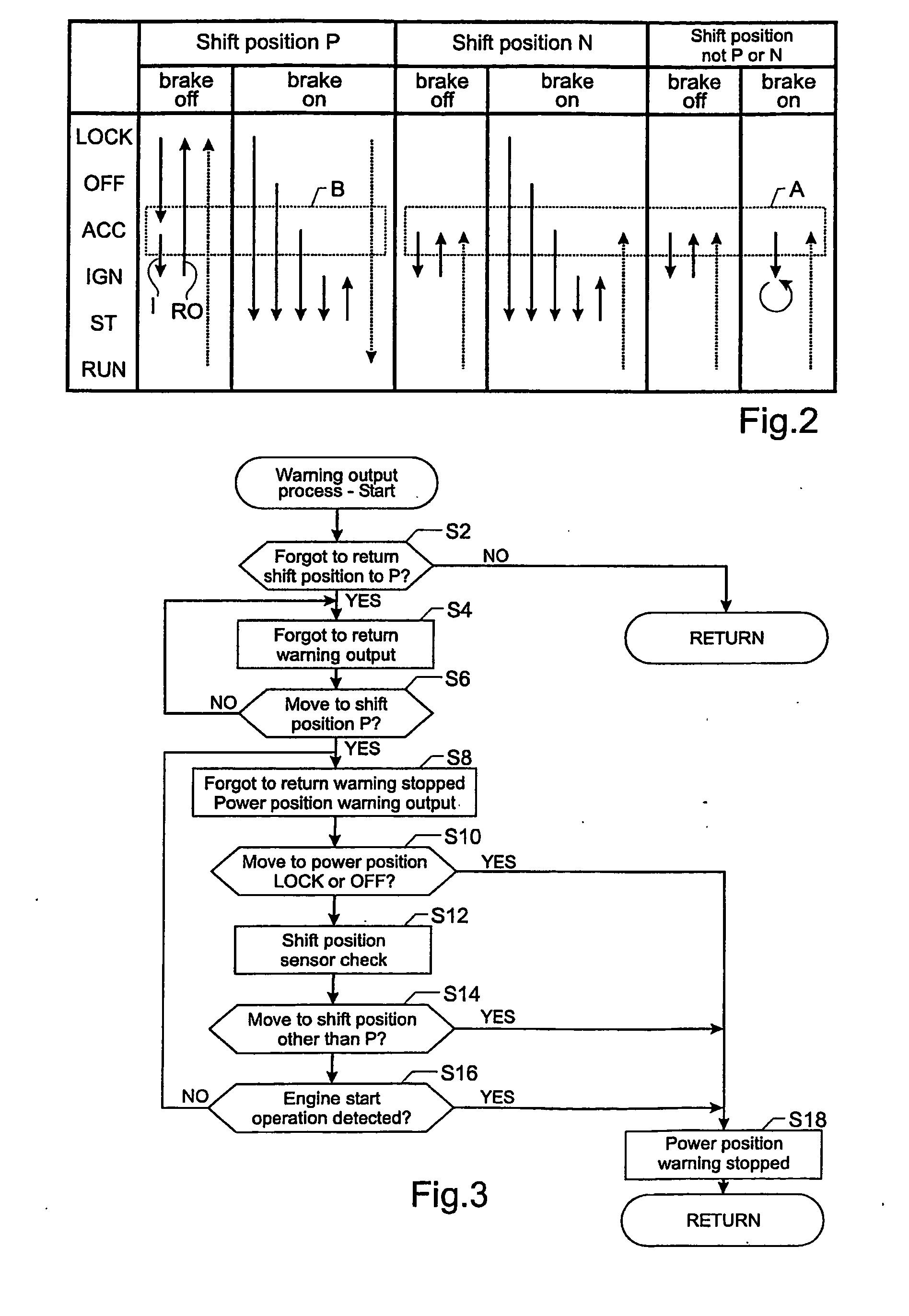
A warning system has a power position detection device, a gear shift position detection device, an alighting detection device, and a power position warning device. The device is operable to provide the power position warning indication when the power position detection device, the gear shift position detection device and the alighting detection device detect that there are preparations for alighting, that the gear shift position is in a P (Park) range and that the power position is in a position other than showing IGNITION OFF. In another aspect, the invention provides a gear shift position warning device. The power position warning device outputs a power position warning indication when the gear shift position detection device detects that the gear shift position has moved to the P range during output of the gear shift position warning indication.

Description

CROSS-REFERENCE TO RELATED APPLICATIONS[0001]This nonprovisional application claims priority under 35 U.S.C. § 119(a) to Japanese Patent Application No. 2004-188279, filed in Japan on Jun. 25, 2004, the entire contents of which are hereby incorporated by reference.BACKGROUND OF THE INVENTION[0002]1. Field of the Invention[0003]This invention generally relates to a system for detecting vehicle power position and outputting a warning indication. The invention also relates to a method of detecting vehicle power position and outputting a warning indication.[0004]2. Background Information[0005]In systems where the vehicle power position is operated by a push-button or the like devices exist that output a warning indication in order to prevent a vehicle driver alighting from the vehicle while forgetting to change the power position to IGNITION-OFF (referred to also as IGN-OFF).[0006]In the following non-patent reference document 1 (Toyota Crown new type vehicle manual September 2003 (page...

Claims


Application Information

Patent Timeline
Patent Type & Authority Applications(United States)
IPC IPC(8): B60Q1/00B60Q9/00B60R25/06B60R25/10B60R25/104B60R25/34
CPCB60Q9/00
Inventor EGUCHI, TAKASHI
Owner NISSAN MOTOR CO LTD
Learn More