Antenna Device and Mobile Radio Apparatus Using the Same

Inactive Publication Date: 2008-10-16
PANASONIC CORP
View PDF2 Cites 8 Cited by
  • Summary
  • Abstract
  • Description
  • Claims
  • Application Information

AI Technical Summary

Benefits of technology

[0008]Satisfying the foregoing formulas allows the directivities in the radiation characteristic to form a characteristic expressed in two “8” letters orthogonal to each other, so that the two “8” letters are switched appropriately for decreasing the directivity effectively.
[0009]The mobile radio apparatus of the present invention comprises the following elements: a first antenna device identical to the foregoing antenna device, a first signal processor; a second antenna device; and a second signal processor. The first signal processor receives/outputs a signal form/to the first antenna devi

Problems solved by technology

The antenna device necessary for this additional radio function must be thus inevitably small in size, so that a balanced or unbalanced type of antenna device has been solely and unavoidably employed.
However, the foregoing balanced or unbalanced type of antenna device solely

Method used


Image

  • Antenna Device and Mobile Radio Apparatus Using the Same
  • Antenna Device and Mobile Radio Apparatus Using the Same
  • Antenna Device and Mobile Radio Apparatus Using the Same

Examples


Example

[0025]3 processor block[0026]8, 12 antenna device[0027]10 receiving circuit block[0028]11 transmitting circuit block[0029]13 tuner block[0030]14 ground plate[0031]15, 16 antenna element 17, 18 inductor element (reactance element)[0032]20 bypass conductor[0033]21, 22 switching element[0034]23 switching circuit[0035]24, 25 feeder section[0036]29 signal detector[0037]37 BER detector[0038]45 level detector

DETAILED DESCRIPTION OF PREFERRED EMBODIMENT

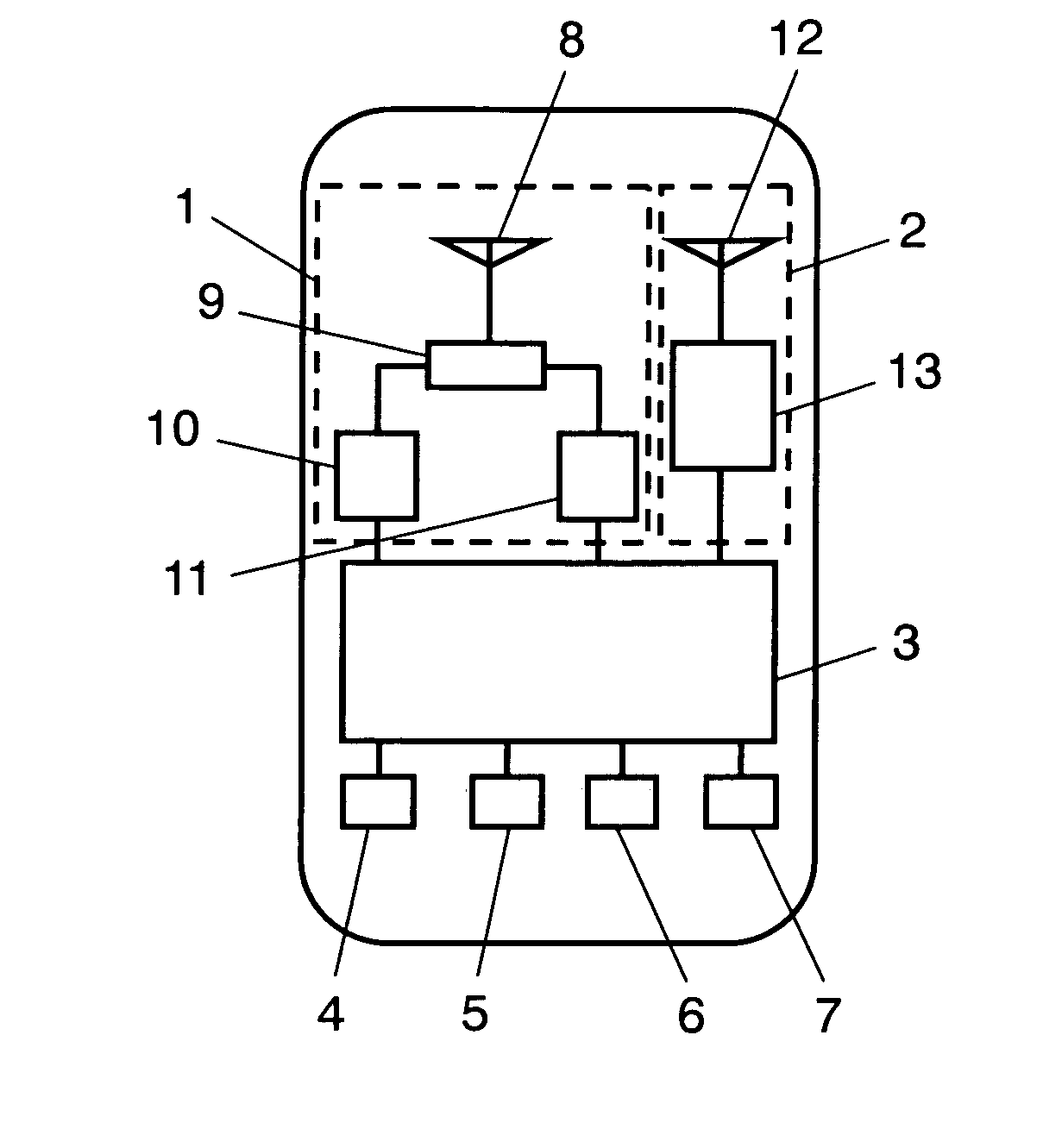
[0039]An exemplary embodiment of the present invention is demonstrated hereinafter with reference to the accompanying drawings. FIG. 1 shows a block diagram illustrating a mobile phone having a television function (TV), this mobile phone is an example of a mobile radio apparatus in accordance with an embodiment of the present invention. In FIG. 1, the mobile radio apparatus comprises telephone block 1, TV block 2, processor block 3, speaker 4, microphone 5, keypad 6, and monitor 7.

[0040]TV block 2 includes antenna device 12 which is a first a...


PUM


Abstract

An antenna device and a mobile radio apparatus using the same antenna device are disclosed. The antenna device includes a ground plate of which short side has a length “a”, a first and a second antenna elements, and a switching circuit. The switching circuit selects whether the first and the second antenna elements are used as a balanced type of antenna or the first antenna is used as an unbalanced type of antenna and the second antenna element is left as a passive element. Assume that wavelength λ1 corresponds to the fundamental frequency of the antenna elements, and wavelength λ2 corresponds to the max. frequency in a usable frequency band, and the antenna elements have electrical length θ which is set at λ1/4. Assume that the first antenna element has physical length L1 smaller than electrical length θ, and the second antenna element has physical length L2. The sum of L1 and L2 is shorter than the short side length “a”, and a half of “a” is smaller than λ2/4.

Description

TECHNICAL FIELD[0001]The present invention relates to antenna devices to be used in mobile radio apparatuses such as mobile phones, and also relates to mobile radio apparatuses using the same antenna devices.BACKGROUND ART[0002]Mobile radio apparatuses recently have gone multifunctional, e.g. a mobile phone has an additional function of receiving television signals for its user to watch the signals on the liquid crystal display built-in the mobile phone.[0003]This additional radio function to mobile radio apparatuses must avoid enlarging the entire size as much as possible. The antenna device necessary for this additional radio function must be thus inevitably small in size, so that a balanced or unbalanced type of antenna device has been solely and unavoidably employed. A conventional antenna device related to the present invention is disclosed in, e.g. Unexamined Japanese Patent Publication No. 2001-251131.[0004]However, the foregoing balanced or unbalanced type of antenna device ...

Claims


Application Information

Patent Timeline
IPC IPC(8): H01Q1/24H01Q3/24
CPCH01Q1/243H01Q3/24H01Q9/16H01Q9/26H01Q9/30H01Q21/24H01Q21/28H01Q1/242H01Q21/0006H04B1/401H04B1/3833
Inventor OKAYAMA, MOTOYUKIYUDA, NAOKINAGATOMI, YOSHITAKAOZEKI, HIROAKI
Owner PANASONIC CORP
Why Eureka
Try Eureka