Telephoto lens system

a telephoto lens and lens group technology, applied in the field of telephoto lens systems, can solve the problems of heavy weight of the lens group to be moved, inability to achieve a higher-speed focusing capability, and inability to move the lens group internally, so as to achieve the effect of shortening the minimum photographic distance and reducing distortion and spherical aberration

Active Publication Date: 2008-10-16
RICOH IMAGING COMPANY
View PDF13 Cites 28 Cited by
  • Summary
  • Abstract
  • Description
  • Claims
  • Application Information

AI Technical Summary

Benefits of technology

[0015]The present invention is to provide a telephoto lens system with an internal-focusing system, by which fluctuations of distortion and those of spherical aberration occurred upon focusing are reduced, and the minimum photographic distance can be made shorter.

Problems solved by technology

In a lens system in which all the lens groups are advanced for focusing, the weight of the lens groups to be moved becomes heavier; and accordingly, such a lens system is not suitable for a higher-speed focusing capability.
However, such an internal-focusing lens group is heavier than the internal-focusing lens groups disclosed in JUPP No.
H06-138385, and is not advantageous for high-speed focusing.
The first lens group of a telephoto lens system is generally known to have an extremely large aperture; and moreover, if the two positive lens elements are made of a special low-dispersion glass (Abbe number of over 80), such an optical arrangement inevitably causes an increase in manufacturing costs.
The cemented lens elements, however, generally increase manufacturing costs, compared with the single (meniscus) lens element.

Method used


Image

  • Telephoto lens system
  • Telephoto lens system
  • Telephoto lens system

Examples


embodiment 1

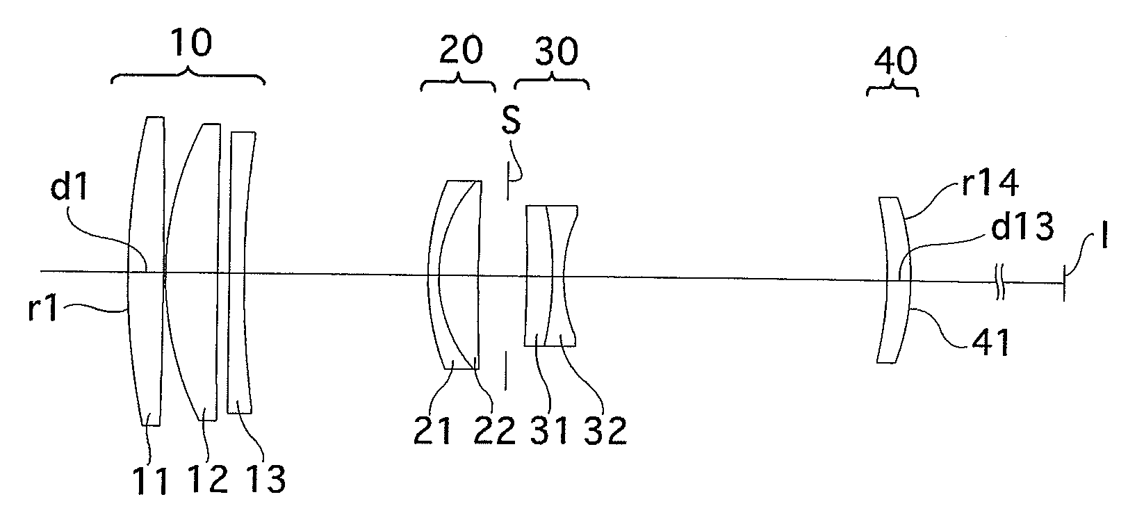
[0098]FIG. 1 shows the lens arrangement of the first embodiment of the telephoto lens system according to the present invention, when an object at infinity is in an in-focus state.

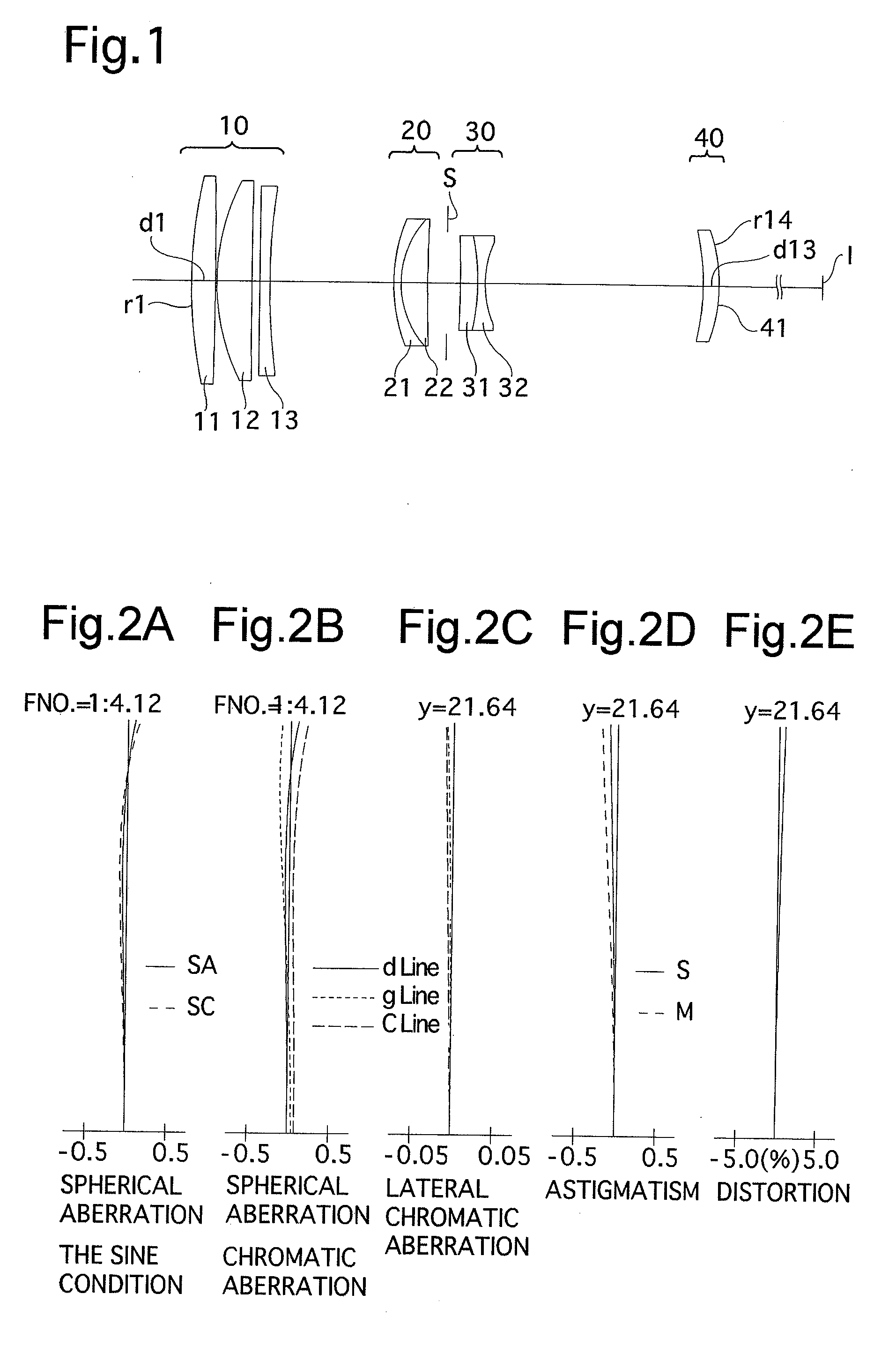
[0099]FIGS. 2A through 2E show aberrations occurred in the lens arrangement shown in FIG. 1, when an object at infinity is photographed.

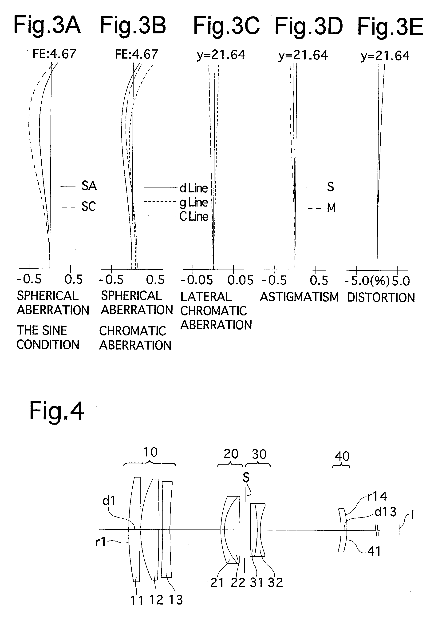
[0100]FIGS. 3A through 3E show aberrations occurred in the lens arrangement shown in FIG. 1, when an object at a closer distance is photographed.

[0101]Table 1 shows the numerical data of the first embodiment.

[0102]The positive first lens group 10 (surface Nos. 1 through 6) includes a positive biconvex lens element (first lens element) 11, a positive meniscus lens element (second lens element) 12 having the convex surface facing toward the object, and a negative lens element (third lens element) 13 having a flat surface facing toward the object, in this order from the object.

[0103]The positive second lens group 20 (surface Nos. 7 through 9) includes a negative meniscus lens...

embodiment 2

[0107]FIG. 4 shows the lens arrangement of the second embodiment of the telephoto lens system according to the present invention, when an object at infinity is in an in-focus state.

[0108]FIGS. 5A through 5E show aberrations occurred in the lens arrangement shown in FIG. 4, when an object at infinity is photographed.

[0109]FIGS. 6A through 6E show aberrations occurred in the lens arrangement shown in FIG. 4, when the object at a closer distance is photographed.

[0110]Table 2 shows the numerical data of the second embodiment.

[0111]In the positive first lens group 10, the first lens element 11 is a positive meniscus lens element having the convex surface toward the object, the second lens element 12 is a positive biconvex lens element, and the third lens element 13 is a negative biconcave lens element. Except the arrangement of the positive first lens group 10, the other lens arrangements are the same as that of the first embodiment.

[0112]The diaphragm S is provided 4.000 in front of (on...

embodiment 3

[0113]FIG. 7 shows the lens arrangement of the third embodiment of the telephoto lens system according to the present invention, when an object at infinity is in an in-focus state.

[0114]FIGS. 8A through 8E show aberrations occurred in the lens arrangement shown in FIG. 7, when an object at infinity is photographed.

[0115]FIGS. 9A through 9E show aberrations occurred in the lens arrangement shown in FIG. 7, when the object at a closer distance is photographed.

[0116]Table 3 shows the numerical data of the third embodiment.

[0117]The basic lens arrangement of the third embodiment is the same as that of the first embodiment.

[0118]The diaphragm S is provided 4.000 in front of (on the object side of) the negative third lens group 30 (surface No. 10).

TABLE 3FNO. = 1:4.1f = 290.98W = 4.2fB = 53.98m = 0.00-−0.02-−0.25Surf. No.rdNdν1159.0148.091.4874970.22−1026.9640.50——379.16210.551.4387595.04948.7399.15——5∞3.501.8040039.56186.30542.15——755.5472.871.7439945.8832.5949.231.4970081.691795.98014.1...


PUM


Abstract

A telephoto lens system includes a positive first lens group, a positive second lens group, a diaphragm, a negative third lens group constituting a focusing lens group, and a positive fourth lens group.
The first lens group includes a positive first lens element, a positive second lens element, and a negative third lens element. The second lens group includes a negative or a positive fourth lens element and a positive or negative fifth lens element which are cemented to each other. The third lens group includes a positive or negative sixth lens element and a negative or positive seventh lens element which are cemented to each other. The fourth lens group includes one positive eighth lens element. Upon focusing on an object at infinity to an object at a closer distance, the third lens group is moved toward the image. The telephoto lens system satisfies the following conditions:
1.4<f/f1<1.8   (1)
2.4<f/f12<3.0   (2)
−5.5<f/f3<−3.5   (3)
    • wherein f: a focal length of the telephoto lens system; f1: the focal length of the first lens group; f12: the combined focal length of the first lens group and the second lens groups; and f3: a focal length of the third lens group.

Description

BACKGROUND OF THE INVENTION[0001]1. Field of the Invention[0002]The present invention relates to a telephoto lens system for use in a single-lens reflex (SLR) camera.[0003]2. Description of the Related Art[0004]In a recent exchangeable lens system for a SLR camera, a high-speed focusing capability is required in order to cope with the automatic focusing system thereof. In order to provide a high-speed focusing capability, the weight of the focusing lens group needs to be lighter.[0005]In a lens system in which all the lens groups are advanced for focusing, the weight of the lens groups to be moved becomes heavier; and accordingly, such a lens system is not suitable for a higher-speed focusing capability.[0006]In known telephoto lens systems, many lens systems employing an internal-focusing system which is arranged to move only a lens group provided in the middle of the telephoto lens system, have been proposed.[0007]For example, in Japanese Unexamined Patent Publication (JUPP) No. H...

Claims


Application Information

Patent Timeline
Patent Type & Authority Applications(United States)
IPC IPC(8): G02B13/02
CPCG02B13/20G02B15/163G02B15/144111
Inventor KATO, KOJI
Owner RICOH IMAGING COMPANY
Why Eureka
Try Eureka