Robotic work cell and method of operation

a robot and work cell technology, applied in the field of robot cells, can solve the problems of time-consuming operation, large cost of robots, and small manufacturers that cannot afford the use of robots

Inactive Publication Date: 2008-10-16
LES MACHINERIES AUTOMATECH
View PDF14 Cites 18 Cited by
  • Summary
  • Abstract
  • Description
  • Claims
  • Application Information

AI Technical Summary

Problems solved by technology

However, because robots are fairly expensive, smaller manufacturers cannot afford the use of robots as their production runs do not justify the cost.
This is a very time-consuming operation and each time the mobile unit is removed from the frame of the robot, the robot is maintained idle for at least the time required to connect another mobile frame thereto.
This is also a labor-intensive operation which is costly and the robot may be rendered idle for long periods of time.

Method used


Image

  • Robotic work cell and method of operation
  • Robotic work cell and method of operation
  • Robotic work cell and method of operation

Examples


Embodiment Construction

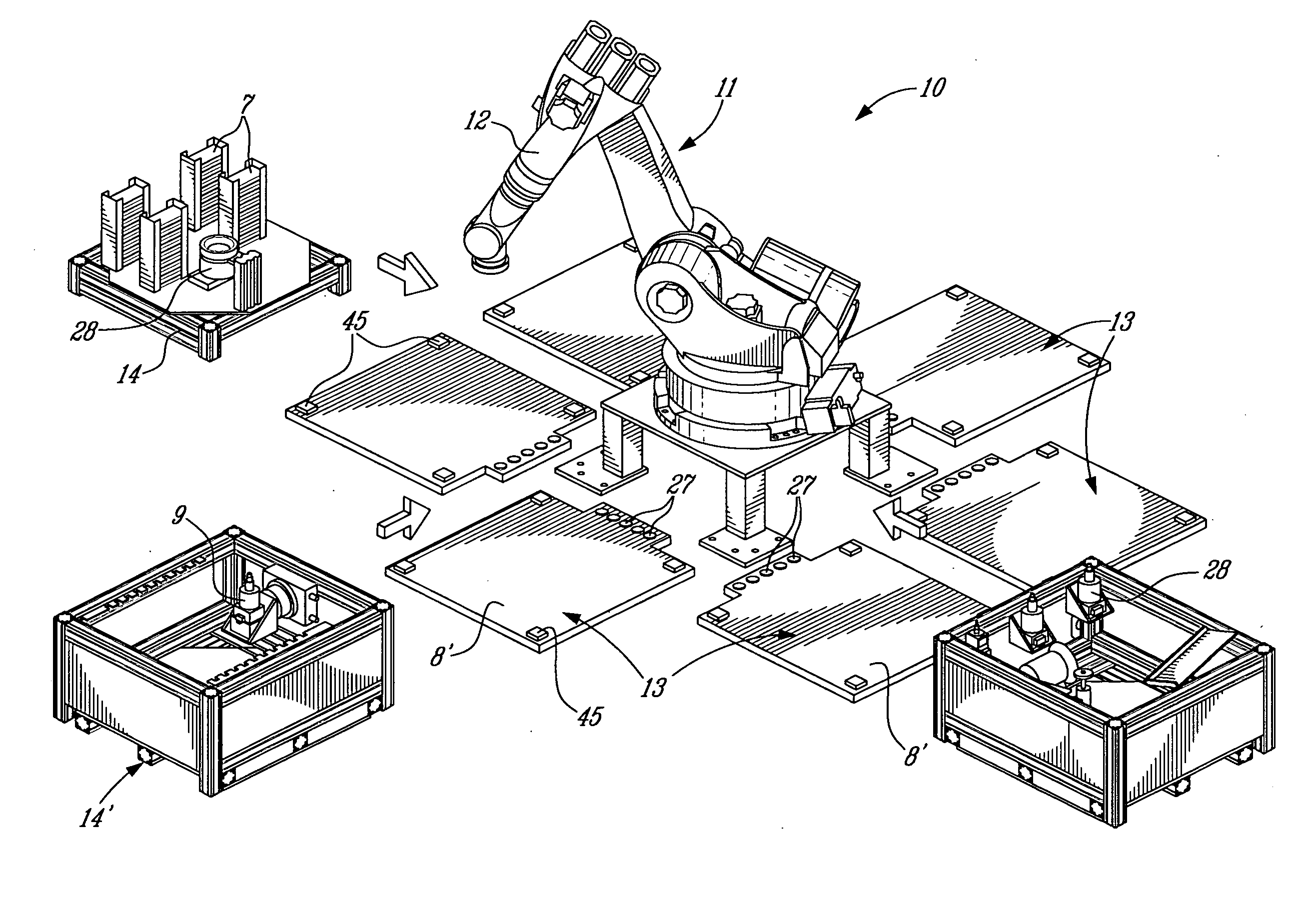
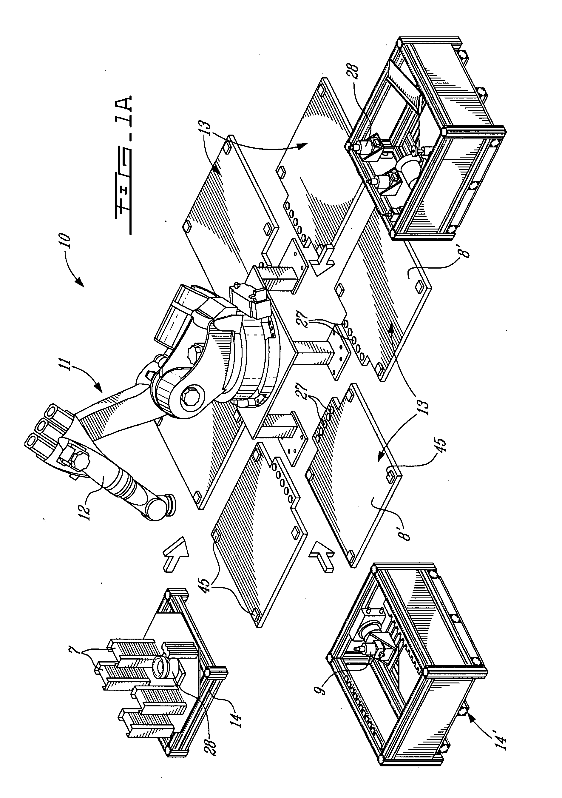
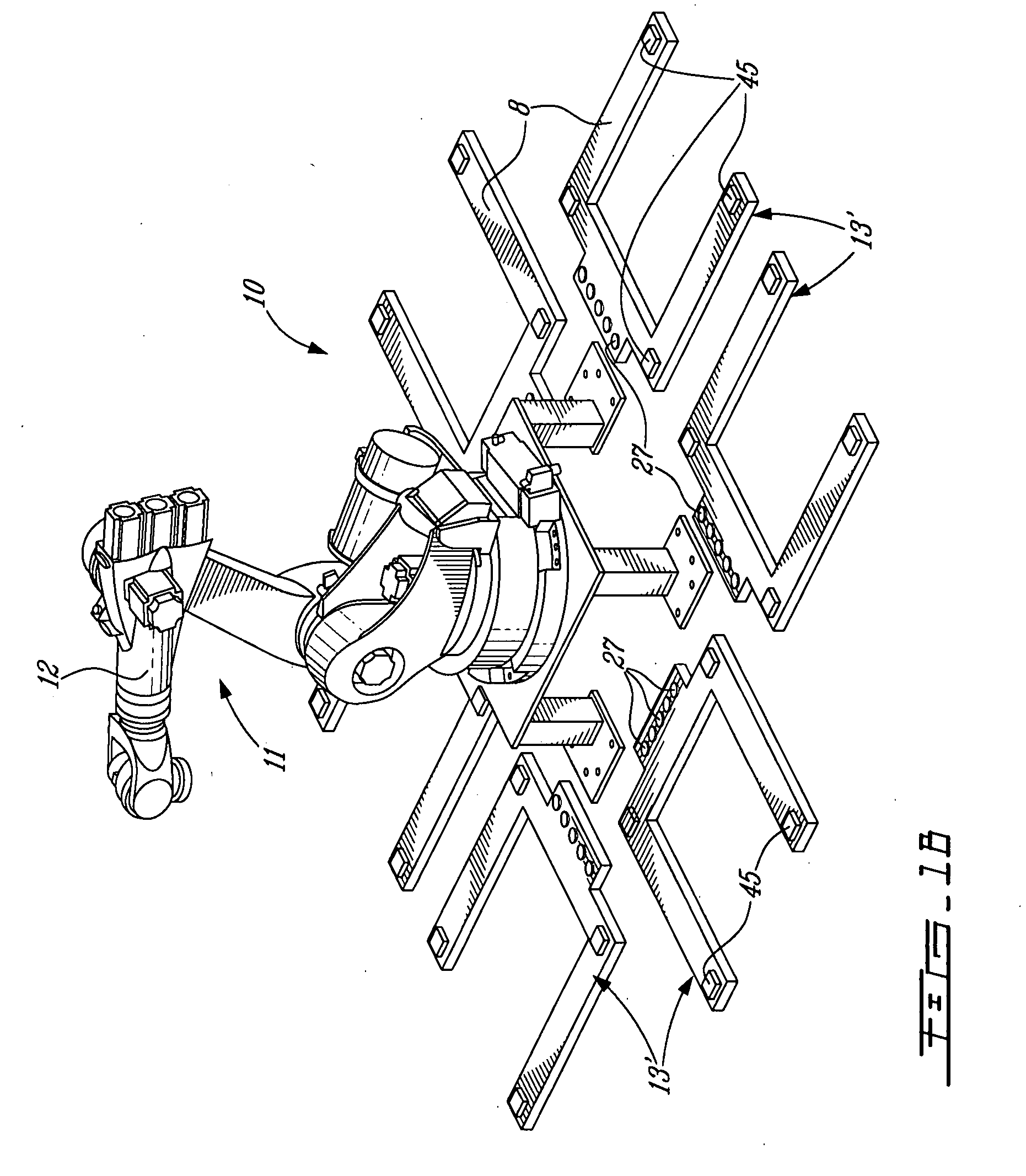
[0020]Referring to the drawings and more particularly to FIGS. 1A to 2B, there is shown generally at 10 the robotic work cell of the present invention. It comprises an industrial robot 11 which is provided with an articulated robotic arm 12. At least two work stations, herein a plurality of work stations 13, are positioned in the work cell 10 at specific locations in proximity to the robot 11. As hereinshown there are two work stations on two of opposed sides of the robot with an additional work station disposed on each of the transverse sides. Accordingly, in this configuration there are six work stations 13 disposed about the robot at specific locations. However, this can vary as will be described later.

[0021]In the configuration as shown in FIGS. 1A to 2B, all of the work stations 13 are provided with work platforms 14 which are detachable from these work stations. As hereinshown one of the detachable work platforms, namely platform 14′, is a work task platform provided with a wo...


PUM


Abstract

A robotic work cell and a method of operation are described. The work cell is comprised of an industrial robot having at least one articulated robotic arm having a tool engaging end. A robot controller is associated with the robot to cause the robot to effect a programmed task selected from a plurality of programmed tasks stored in a computer memory. At least two or more fixed work stations are positioned in the work cell in proximity of the robot. At least two of the work stations have a work task platform detachably secured thereto with at least one of said platforms being a work task platform. The work platforms have a software associated therewith for the robot to effect an associated one of the programmed tasks on a product. The programmed task is one of a series of programmed tasks which are related and associated with a specific product to transform said product.

Description

TECHNICAL FIELD[0001]The present invention relates to a robotic cell and a method of operation and more specifically, but not exclusively, to a robotic cell in which a robot is operated to perform one of a series of programmed tasks on work platforms, some of which are removably secured to specific ones of a plurality of fixed work stations in the immediate area of the robot.BACKGROUND ART[0002]Currently industrial robots are used to perform fixed respective tasks such as welding of component parts together, cutting, drilling or routing a piece of material, such as wood, and the like wherein the robot always repeats a specific programmed task. The products which are usually worked on by the robot have a specific support structure capable of supporting the product at a precise location which is dedicated to the robot. Accordingly, these robots are set up to perform repetitive tasks. Accordingly, in a production run, once that specific task has been completed, the robot can be idled f...

Claims


Application Information

Patent Timeline
Patent Type & Authority Applications(United States)
IPC IPC(8): B65G1/00
CPCB23P21/004B25J9/0093
Inventor BERGERON, LOUIS
Owner LES MACHINERIES AUTOMATECH
Why Eureka
Try Eureka