
LED driver with current sink control and applications of the same g

Active Publication Date: 2008-10-23
AU OPTRONICS CORP
View PDF6 Cites 42 Cited by
  • Summary
  • Abstract
  • Description
  • Claims
  • Application Information

AI Technical Summary

Benefits of technology

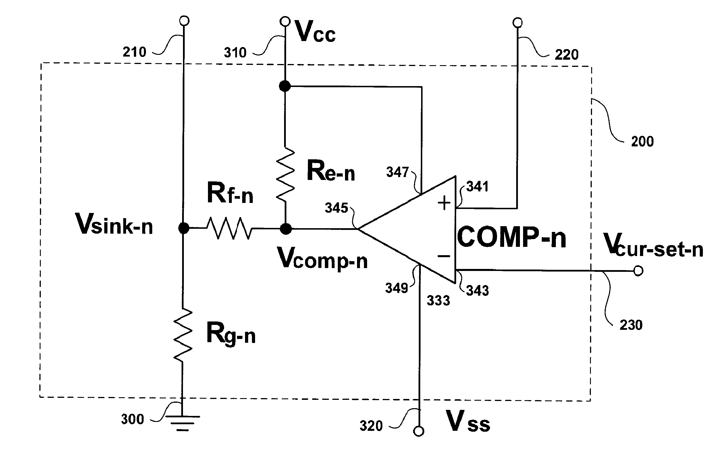
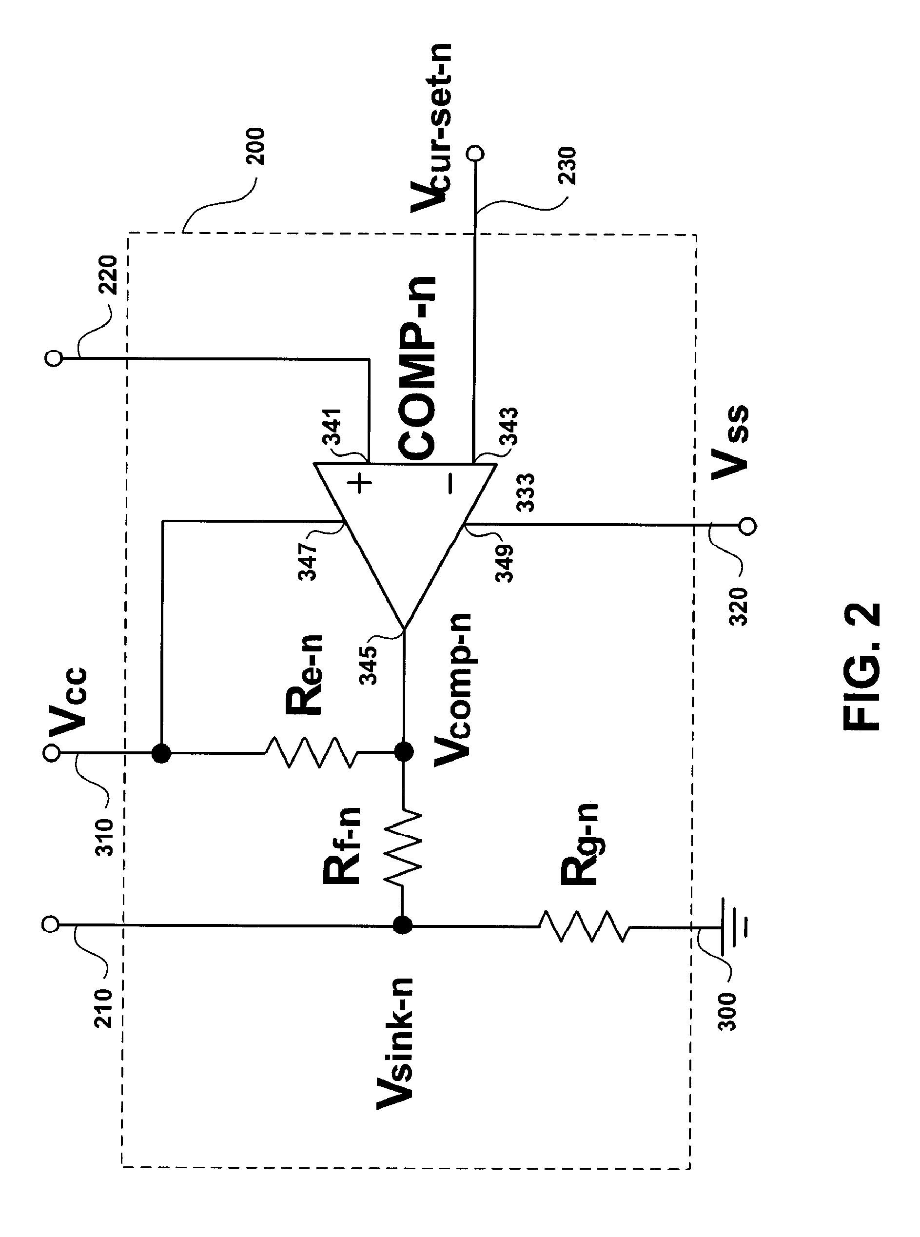
[0052]When the output voltage of the n-th current feedback unit CFn is greater than the predetermined DC voltage electrically coupled to the third input of the n-th current compensation unit CCn, the output of the comparator of the n-th current compensation unit CCn provides a positive voltage to cause a compensation current to flow from the second terminal to the first terminal of the seventh resistor. When the output voltage of the n-th current feedback unit CFn is less than the predetermined DC voltage electrically coupled to the third input of the n-th current compensation unit CCn, the output of the comparator of the n-th current compensation unit CCn provides a negative voltage to cause a compensation current to flow from the first terminal to the second terminal of the seventh resistor. The current of each of the N LED columns of the backlight system is individually controllable and precisely compensatable.

Problems solved by technology

However, such a driving device consumes a large sum of electrical energy and produces large amounts of heat during operation.
Additionally, this LED driving device can only be used for a single color LED backlight.
The range of controllable current through the LED clusters is limited.
Such a driving device also consumes a large sum of electrical energy and produces large amounts of heat during operation.
Therefore, a heretofore unaddressed need exists in the art to address the aforementioned deficiencies and inadequacies.

Method used


Image

  • LED driver with current sink control and applications of the same g
  • LED driver with current sink control and applications of the same g
  • LED driver with current sink control and applications of the same g

Examples


Embodiment Construction

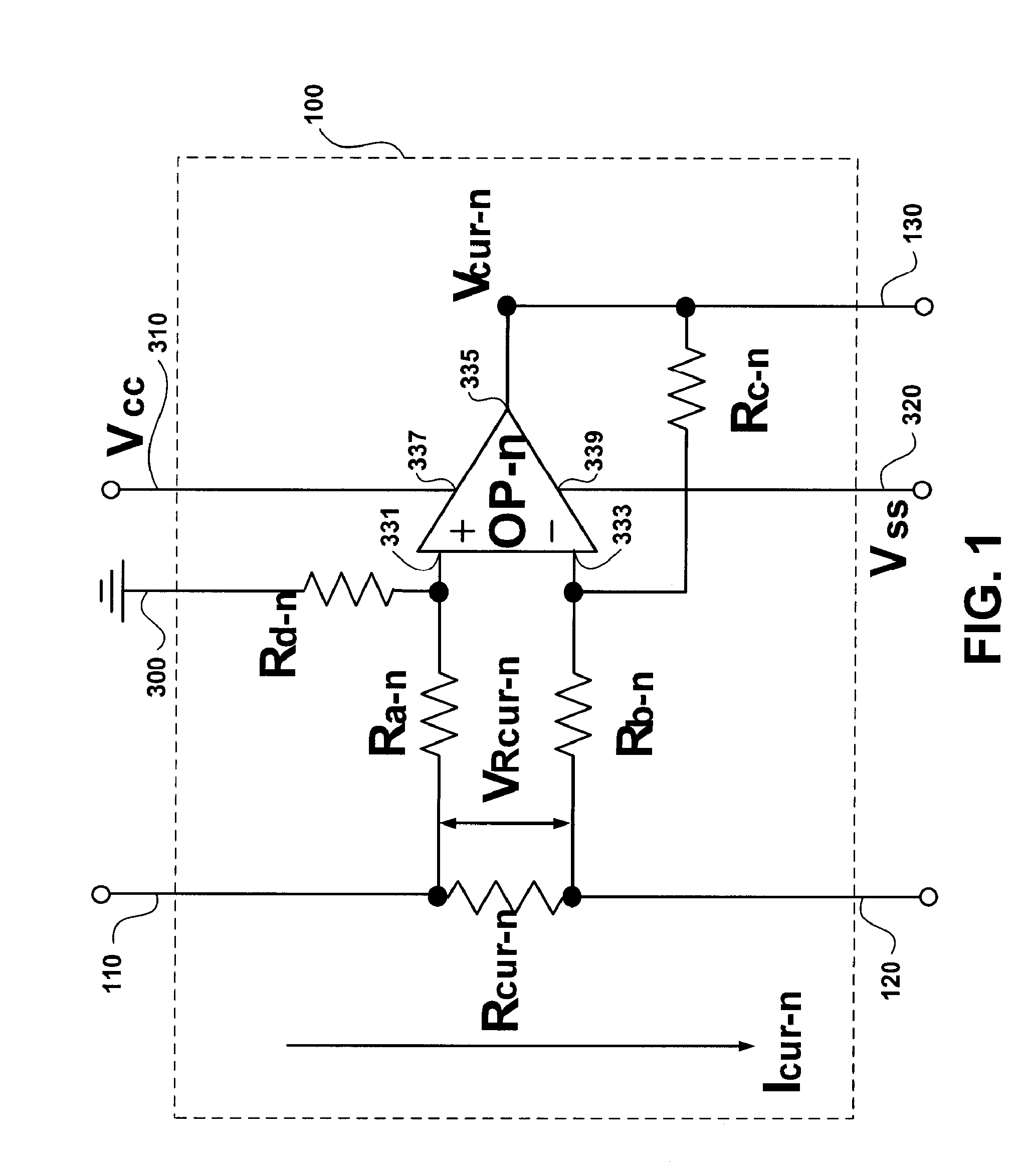
[0063]The present invention is more particularly described in the following examples that are intended as illustrative only since numerous modifications and variations therein will be apparent to those skilled in the art. Various embodiments of the invention are now described in detail. Referring to the drawings, like numbers indicate like components throughout the views. As used in the description herein and throughout the claims that follow, the meaning of “a”, “an”, and “the” includes plural reference unless the context clearly dictates otherwise. Also, as used in the description herein and throughout the claims that follow, the meaning of “in” includes “in” and “on” unless the context clearly dictates otherwise.

[0064]The description will be made as to the embodiments of the present invention in conjunction with the accompanying drawings in FIGS. 1-8. In accordance with the purposes of this invention, as embodied and broadly described herein, this invention, in one aspect, relate...


PUM


Abstract

A backlight system for use in an LCD display with a driver providing current sink control includes an LED array module, a current feedback circuit, and a current compensation circuit. The LED array module has N columns of LEDs and each LED column has M LEDs connected in serial, wherein the current feedback circuit includes N current feedback units and the current compensation circuit includes N current compensation units, both of the current feedback circuit and the current compensation circuit being electrically coupled to the LED array module. When the backlight system is in operation, a current passes through an LED column, a current feedback unit, and a current compensation unit to generate an output voltage that is used for comparison with a predetermined DC voltage, and the current is compensated based on the results of the comparison.

Description

FIELD OF THE INVENTION[0001]The present invention relates generally to a light emitting diode driver, and more particularly, to a light emitting diode driver with current sink control for a liquid crystal display.BACKGROUND OF THE INVENTION[0002]A liquid crystal display (hereinafter “LCD”) usually requires a cold cathode fluorescent lamp to provide backlight to display an image on an LCD screen. In recent years, light emitting diode (hereinafter “LED”) array modules have emerged as a new backlight source and it becomes increasingly popular because it provides more vivid and brighter color images.[0003]An LED array module is generally configured as an I×J LEDs array, where I=1, 2, . . . N, J=1, 2, . . . M, and N and M are positive integers. An LED array module includes N columns of LED, where each LED column has M individual LEDs. Usually, each LED in an LED column is electrically coupled in serial. The anode of the first LED forms a first terminal of the LED column, and the cathode ...

Claims


Application Information

Patent Timeline
IPC IPC(8): H05B37/02H05B37/00H01L33/00
CPCH05B33/0827H05B33/0857H05B45/46H05B45/20
Inventor SHIH, HUNG-MINLEE, TSUNG-SHIUNSUN, CHIA-HUNGLIN, HUANG-DE
Owner AU OPTRONICS CORP
Learn More