Amplifying apparatus

a technology of amplifying apparatus and amplifier, which is applied in the direction of phase-modulated carrier system, modulation, gain control, etc., can solve the problems of white quantization noise being the main noise source, the specification of acpr may not be satisfied, and the noise level of an amplifying apparatus using the eer method or the et method is higher than that of a normal linear amplifying apparatus. achieve high quality and high frequency high

Active Publication Date: 2008-10-23
NEC CORP
View PDF2 Cites 115 Cited by
  • Summary
  • Abstract
  • Description
  • Claims
  • Application Information

AI Technical Summary

Benefits of technology

[0034]It is an object of the present invention to provide a highly effective and high quality high frequency amplifying apparatus.

Problems solved by technology

However, there is a problem that a noise level of an amplifying apparatus using the EER method or the ET method is higher than that of a normal linear amplifying apparatus.
When the delta modulation is used as the pulse modulating method, a white quantization noise is the main noise source.
If the SNR is degraded by noise induced in pulse modulator 902, the specification for the ACPR may not be satisfied.
However, if these techniques are adopted, problems will occur in which electric power consumption of a signal processing circuit in pulse modulator 902 is increased, loss induced when switching amplifier 903 is switched is increased, and electric power consumption of the entire EER amplifier is increased.

Method used


Image

  • Amplifying apparatus
  • Amplifying apparatus
  • Amplifying apparatus

Examples


first exemplary embodiment

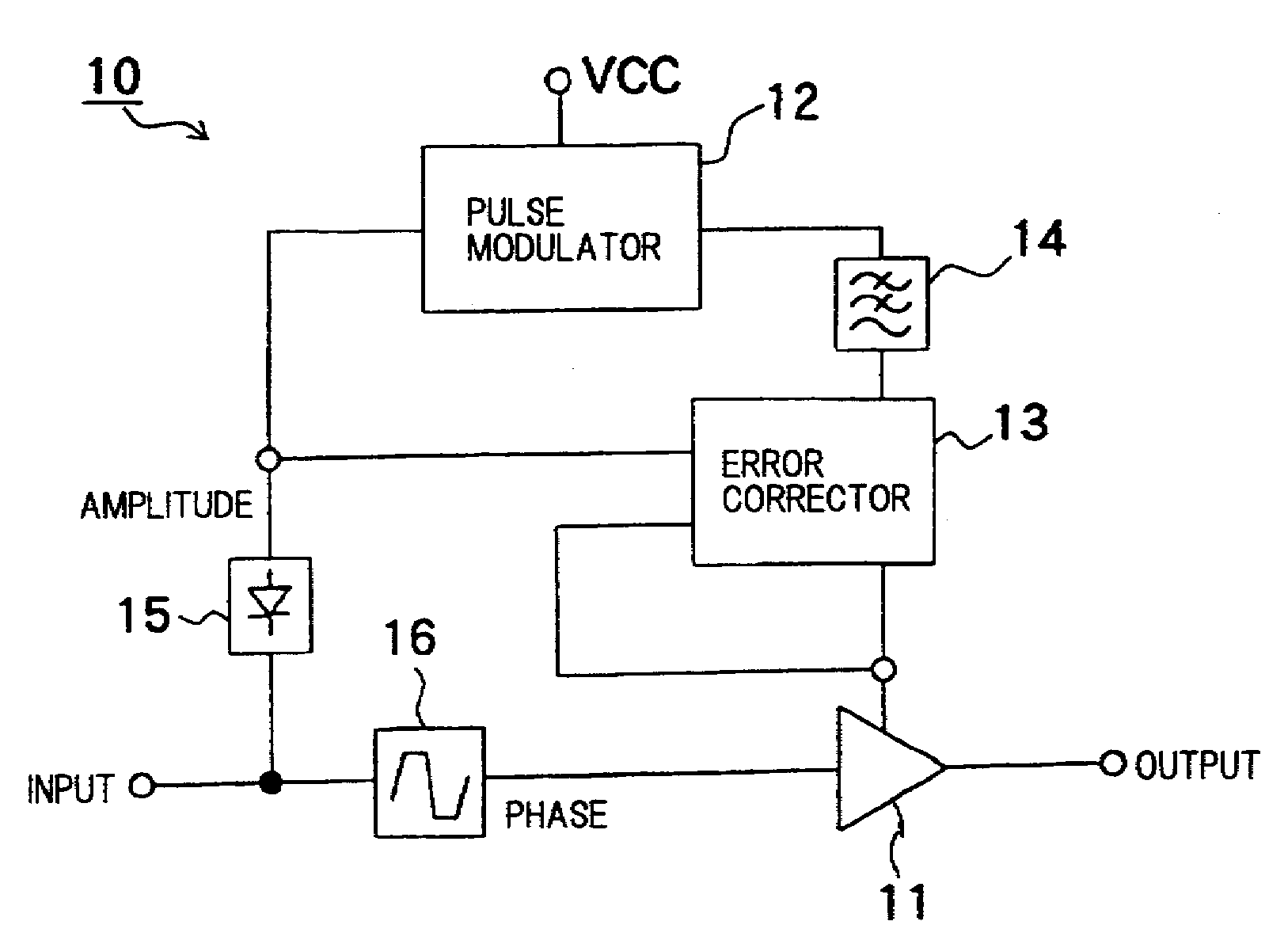
[0057]FIG. 3 is a block diagram illustrating a configuration of a high frequency amplifying apparatus according to a first exemplary embodiment. Referring to FIG. 3, high frequency amplifying apparatus 10 is an EER amplifier including RF amplifier 11, first pulse modulator 12, error corrector 13, low-pass filter 14, envelope detector 15, and limiter 16.

[0058]A digital-modulated high frequency input analog signal which is inputted to high frequency amplifying apparatus 10 is caused to branch to two signals. One signal of the two signals is inputted to envelope detector 15, and the other signal is inputted to limiter 16.

[0059]Envelope detector 15 eliminates a carrier frequency component from the inputted signal, and extracts an amplitude component (envelope). An output of envelope detector 5 is inputted to pulse modulator 2 and error corrector 13.

[0060]First pulse modulator 12 pulse-modulates and amplifies a signal from envelope detector 15 to output the signal to low-pass filter 14. ...

second exemplary embodiment

[0108]In high frequency amplifying apparatus 10 of the first exemplary embodiment illustrated in FIG. 3, error corrector 13 uses the amplitude signal which is not mixed with the phase signal from limiter 16 and which is provided from low-pass filter 14 to correct an error. However, the present invention is not limited to this configuration. As another configuration example, error corrector 13 may extract the amplitude component from a high frequency output signal which is obtained by mixing the amplitude signal from low-pass filter 14 and the phase signal from limiter 16 in RF amplifier 11, and may use the amplitude component to correct the error.

[0109]FIG. 9 is a block diagram illustrating a configuration of a high frequency amplifying apparatus according to a second exemplary embodiment. Referring to FIG. 9, high frequency amplifying apparatus 20 includes RF amplifier 11, first pulse modulator 12, error corrector 13, low-pass filter 14, envelope detector 15, limiter 16, and envelo...

third exemplary embodiment

[0121]In the first exemplary embodiment, a configuration is described in which the amplitude component is extracted by envelope detector 15, and the phase component is extracted by limiter 16 from the high frequency input signal, however, the present invention is not limited to this configuration. If a base band section is configured to be able to output the amplitude signal and the phase signal, the high frequency amplifying apparatus may directly use those signals. If so, extraction of the amplitude signal by envelope detector 15 and extraction of the phase signal from the high frequency input signal, become unnecessary, so that the size of circuit is reduced.

[0122]FIG. 11 is a block diagram illustrating a configuration of a high frequency amplifying apparatus according to a third exemplary embodiment. Referring to FIG. 11, high frequency amplifying apparatus 30 includes RF amplifier 11, first pulse modulator 12, error corrector 13, low-pass filter 14, and frequency converter 19. ...


PUM


Abstract

A pulse modulator generates a pulse-modulated signal by pulse-modulating and amplifying the amplitude component of an input signal. A low-pass filter filters the pulse-modulated signal from the pulse modulator, and generates an amplified amplitude signal which is obtained by amplifying the amplitude component. An error corrector generates a corrected amplitude signal by correcting an error of the amplified amplitude signal from the low-pass filter by using the amplitude component of the input signal. A mixing unit generates the output signal by mixing the corrected amplitude signal from the error corrector and the phase component of the input signal.

Description

[0001]This application is a continuation-in-part of PCT / JP2006 / 325037 filed on Dec. 12, 2006, which is based upon and claims the benefit of priority from Japanese Patent Applications No. 2006-002459 filed on Jan. 10, 2006. Additionally, this application is based upon and claims the benefit of priority from Japanese Patent Applications No. 2006-335657 filed on Dec. 13, 2006. The contents of the two Japanese Applications and the PCT application are incorporated herein by this reference.BACKGROUND OF THE INVENTION[0002]1. Field of the Invention[0003]The present invention relates to an amplifying apparatus, specifically, to an amplifying apparatus amplifying a signal including an amplitude component and a phase component.[0004]2. Description of the Related Art[0005]In recent years, a digital modulating method such as QPSK (Quadrature Phase Shift Keying) and multiple-value QAM (Quadrature Amplitude Modulation) has been used for wireless communication. In the QPSK and the multiple-value Q...

Claims


Application Information

Patent Timeline
Patent Type & Authority Applications(United States)
IPC IPC(8): H03C3/04
CPCH03C5/00H03F1/0227H03F3/217H03F2200/102H03F2200/432
Inventor KUNIHIRO, KAZUAKITAKAHASHI, KIYOHIKO
Owner NEC CORP
Why Eureka
Try Eureka