Multi-media recess data low voltage box with slide-away hidden cover

a low-voltage box and data technology, applied in the direction of electrical apparatus casings/cabinets/drawers, lighting conductor installation, coupling device connection, etc., can solve the problems of affecting the safety of personnel, affecting the installation and service of components inside the box, and restricting access to the interior. , to achieve the effect of convenient access

Active Publication Date: 2008-10-30
THOMAS & BETTS INT INC
View PDF25 Cites 60 Cited by
  • Summary
  • Abstract
  • Description
  • Claims
  • Application Information

AI Technical Summary

Benefits of technology

[0011]The body can include first and second ledges that extend into the interior of the body from the first and second end walls. A ledge can also extend into the interior from the second side wall. When the cover is in the closed position, the ledges are contacted by the cover and provide support for the cover. In a preferred embodiment, the back wall...

Problems solved by technology

However, when the cover is in the open position, it can restrict access to the interior of the box and make it more difficult for a user to install and service compon...

Method used


Image

  • Multi-media recess data low voltage box with slide-away hidden cover
  • Multi-media recess data low voltage box with slide-away hidden cover
  • Multi-media recess data low voltage box with slide-away hidden cover

Examples


first embodiment

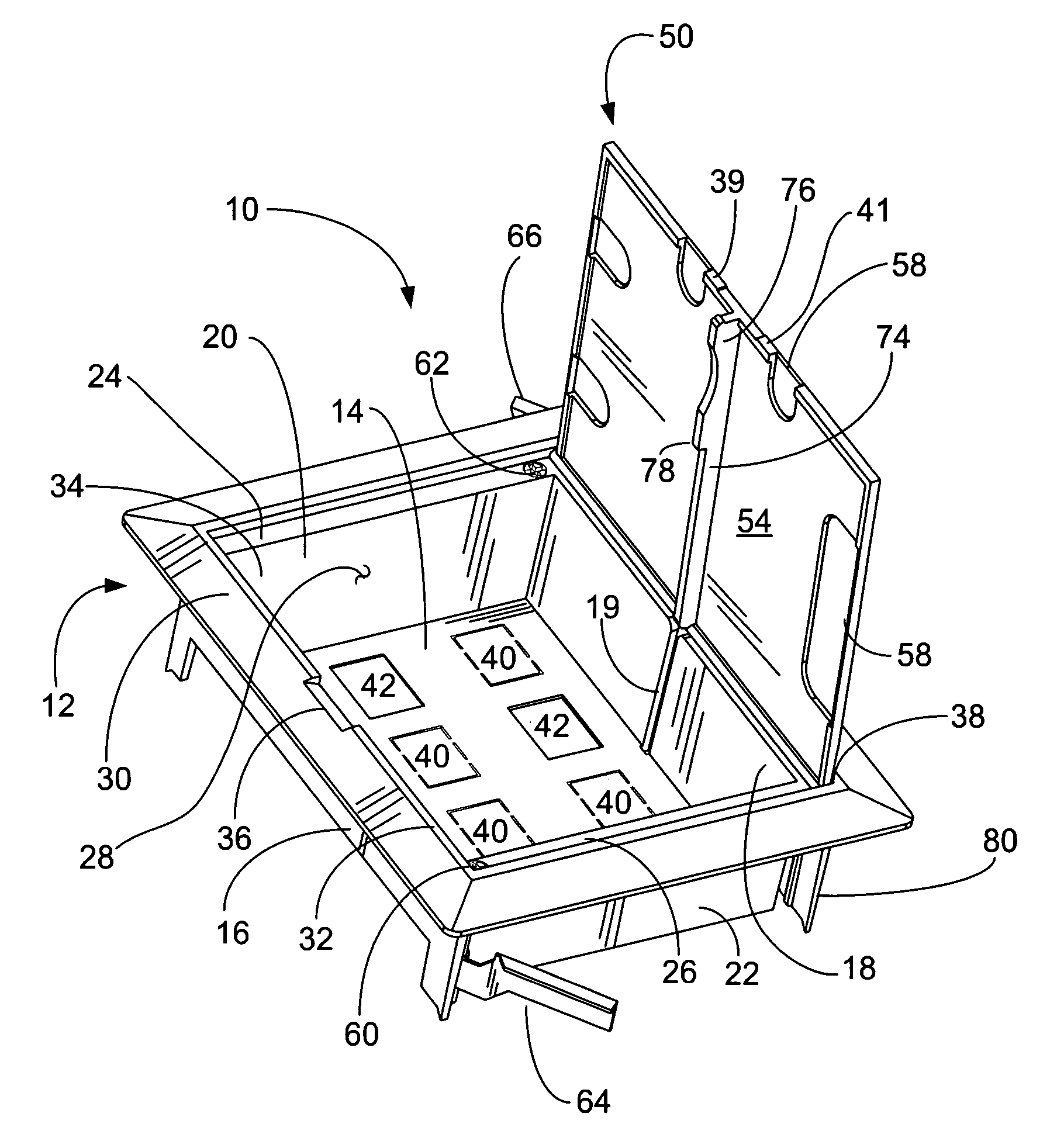
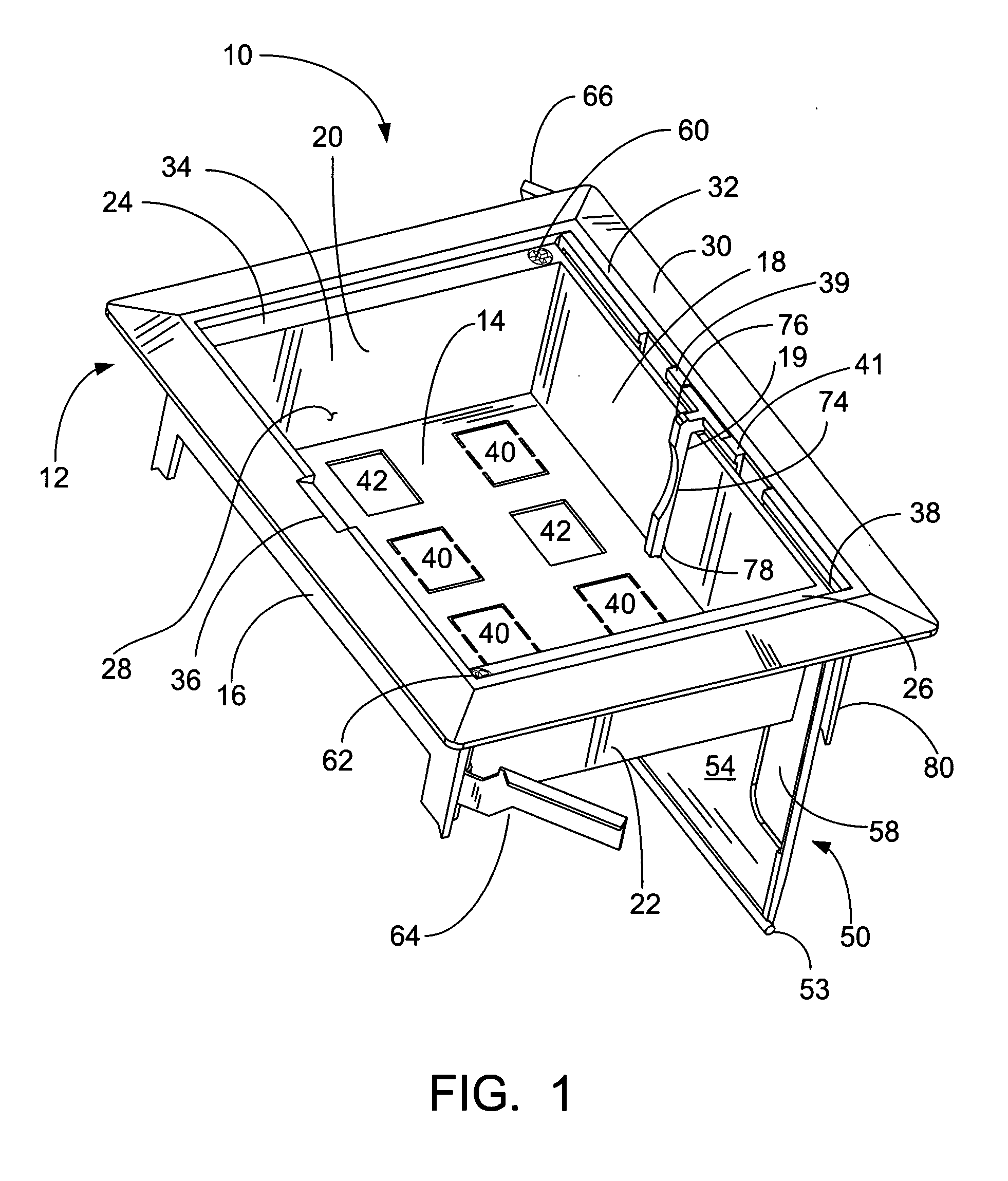
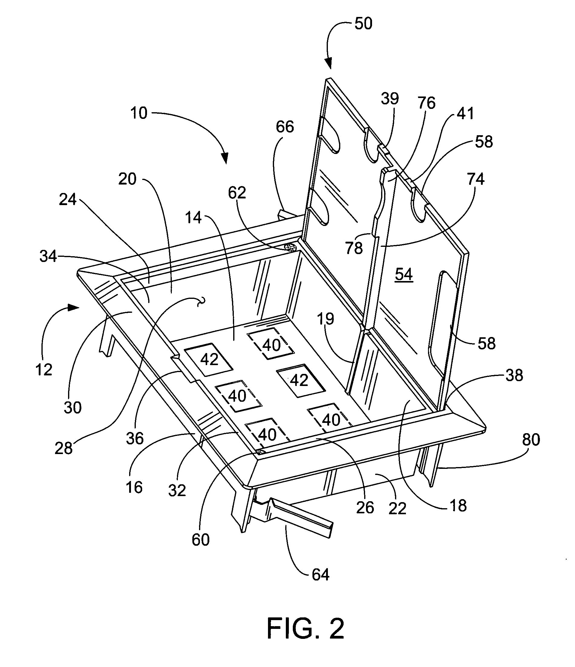
[0032]Referring to the drawings, FIG. 1 shows the electrical box 10 that includes a body 12 and a cover 50. The body 12 is generally rectangular in shape and has a back wall 14 and a face plate 30 connected by a perimeter wall, which is formed by a pair of side walls 16, 18 and a pair of end walls 20, 22. Each of the end walls 20, 22 has a ledge 24, 26 that connects the top of each end wall 20, 22 to the face plate 30. The face plate 30 has an opening 34 for accessing the interior 28 of the box 10 and a recessed edge 32 that extends around the perimeter of the opening 34. The cover 50 is shown inserted in a slot 38 adjacent one of the side walls 18 and the recessed edge 32 of the face plate 30, referred to herein as the “fully retracted position.” The face plate 30 extends outwardly from the top of the perimeter wall at a substantially right angle to the side walls 16, 18 and end walls 20, 22 and is used to mount the electrical box 10 in a ceiling, wall or floor. The shape of the co...

second embodiment

[0044]FIG. 6 is a rear view of the electrical box 110 and it shows the rail 174 on the inside surface 154 of the cover 150 as it passes through the track 119 in the side wall 118 (FIG. 5). The rail 174 guides the cover 150 so that it stays aligned as it is retracted into the electrical box 110. The interior surface 154 of the cover 150 can have one or more knockouts 158 that are removed to provide openings for wires and / or cables (not shown) to enter and leave the body 112. In addition, all of the removable elements 140, 141 (see FIG. 5) are removed to provide apertures 142, 143 in the back wall 114 and transition wall 117, respectively.

[0045]FIG. 6 also illustrates the operation of the rotatable mounting brackets 164, 166 which are shown in a partially extended position. Each of the rotatable mounting brackets 164, 166 includes a tapped cylindrical base 168, 169 that receives a mounting screw 160, 162 (FIG. 5) and an arm 170, 172 extending outwardly from the cylindrical base 168. T...


PUM


Abstract

An electrical box and cover that includes a body having a back wall, a face plate and a perimeter wall which define an interior and an exterior for the body. The back wall has one or more removable elements for forming apertures that can be used to mount connectors. The faceplate has an opening for accessing the interior that extends beyond the perimeter wall to expose a slot. The cover is connected to the body by one or more hinges and is pivotably movable between an open and closed position. When the cover is in the open position, it can be retracted into the housing. A housing extending from the rear of the face plate on the exterior of the body receives the cover. The cover can include a rail on the interior surface and the perimeter wall can include a track that receives the rail when the cover is retracted into the box.

Description

[0001]This application claims priority from provisional application Ser. No. 60 / 926,574, filed on Apr. 27, 2007, and provisional application Ser. No. 60 / 927,075, filed on May 1, 2007, both of which are incorporated herein in their entirety.FIELD OF THE INVENTION[0002]The invention relates to a recessed, in-wall, electrical connector box for low voltage wiring that includes a flip-up cover. In particular, the invention relates to a recessed, in-wall, electrical connector box for low voltage wiring that includes a flip-up cover that can be retracted into the box.BACKGROUND OF INVENTION[0003]Electrical outlet boxes for housing electrical fixtures, such as switches and receptacles, are well known. Electrical outlet boxes typically have openings for inserting electrical wires into the box so that they can be terminated to the electrical fixtures inside. The fixtures are mounted inside the box in a manner that provides protection for the fixtures as well as the wire terminations. Such out...

Claims


Application Information

Patent Timeline
IPC IPC(8): H05K5/03
CPCH02G3/123H02G3/185Y10S248/906
Inventor DINH, CONG THANHJOLLY, ROBERT KEVIN
Owner THOMAS & BETTS INT INC
Why Eureka
Try Eureka