Variable frequency reduced speed variation electric drive

a technology of electric drives and variable frequency, applied in the direction of motor/generator/converter stoppers, dynamo-electric converter control, polyphase induction motor starters, etc., can solve the problems of low weight and cost, high reliability, cost, weight, volume, and reliability of power electronics that are still not affordable for variable frequency applications, and achieve the effect of minimizing the speed variation of a motor

Inactive Publication Date: 2008-10-30
HONEYWELL INT INC
View PDF22 Cites 19 Cited by
  • Summary
  • Abstract
  • Description
  • Claims
  • Application Information

AI Technical Summary

Benefits of technology

[0010]In another aspect of the present invention, a method for minimizing speed variation of a motor driven by a variable frequency power distribution system comprises feeding power from the power distribution system into a motor controller; monitoring a frequency of the power with the motor controller; delivering the power to a first set of windings having a first number of poles when the frequency is within a first frequency range; and delivering the power to a second set of windings having a second number of poles when the frequency is within a second frequency range, wherein the first number of poles is greater than the second number of poles; at least a portion of the first frequency range is greater than the second frequency range; and at least a portion of the first frequency range overlaps with a portion of the second frequency range.

Problems solved by technology

Hence, simple electric drives without solid-state power electronics are obtained, resulting in low weight and cost and high reliability.
However the cost, weight, volume, and reliability of power electronics are still not affordable for application in variable frequency situations.
In addition, additional forced cooling is often required to prevent the power electronics from overheating.

Method used


Image

  • Variable frequency reduced speed variation electric drive
  • Variable frequency reduced speed variation electric drive
  • Variable frequency reduced speed variation electric drive

Examples


Embodiment Construction

[0019]The following detailed description is of the best currently contemplated modes of carrying out the invention. The description is not to be taken in a limiting sense, but is made merely for the purpose of illustrating the general principles of the invention, since the scope of the invention is best defined by the appended claims.

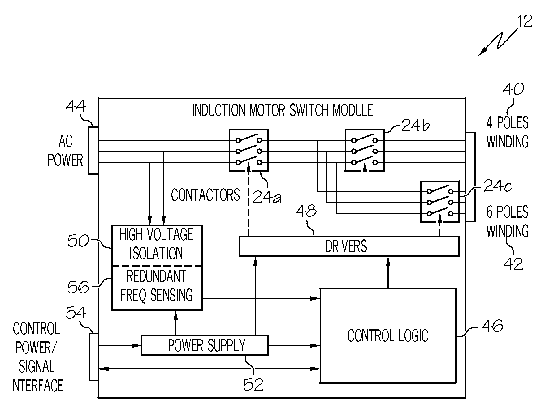
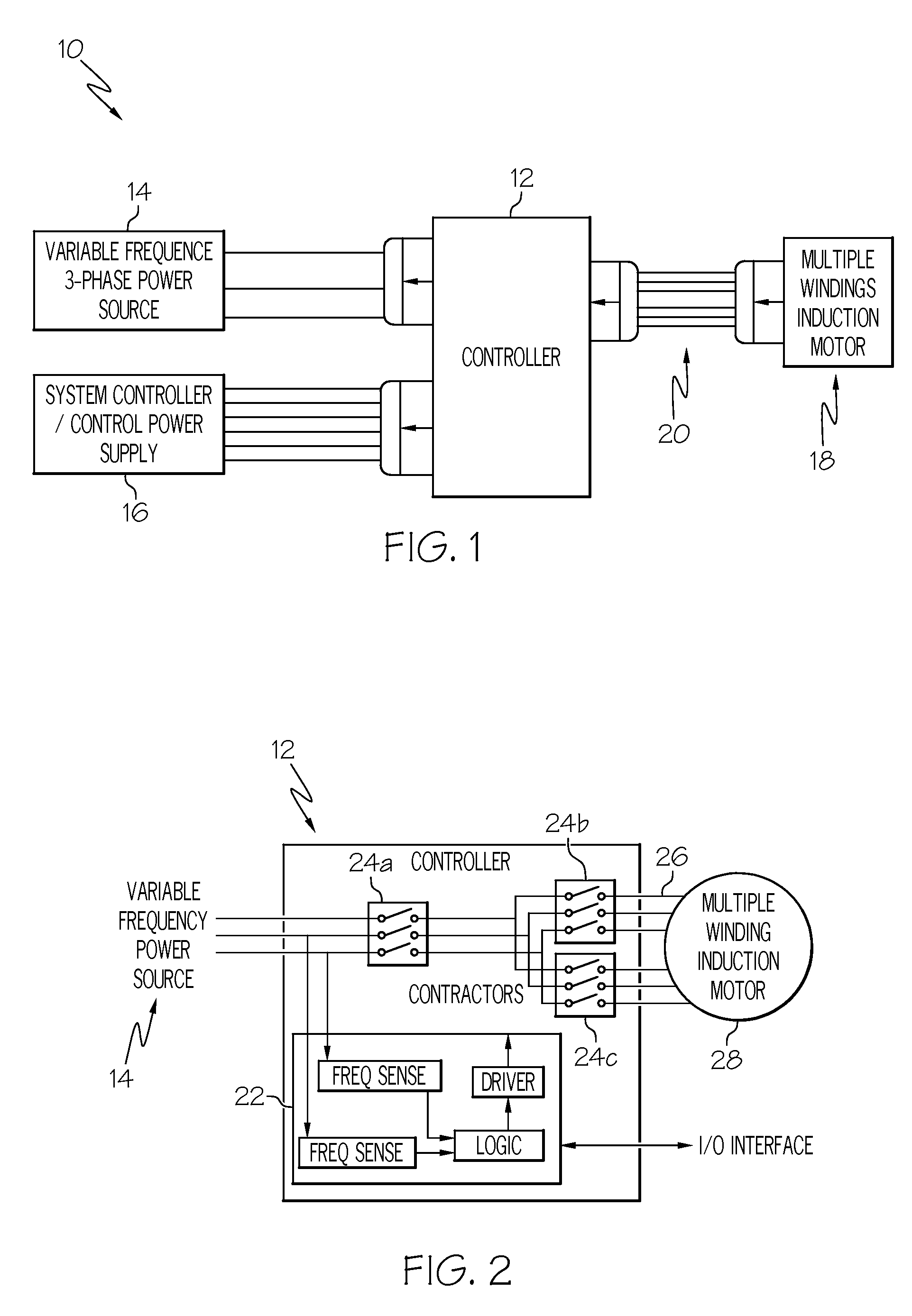
[0020]Broadly, the present invention provides apparatus and methods for obtaining a reduced-speed-variation electric drive when using a variable-frequency power distribution system. The apparatus and methods may use a multiple-winding induction machine. Each winding may have a different number of poles. The winding with the smallest number of poles may operate the machine at the lowest bus frequency, while the winding with the largest number of poles may operate the machine at the highest bus frequency. In one embodiment, a third winding, with a middle number of poles, may operate the machine at the middle frequency ranges. The speed of the induction ma...


PUM


Abstract

A multiple-winding induction machine may be used to obtain a reduced-speed-variation electric drive when using a variable-frequency power distribution system. Each winding may have a different number of poles. The winding with the smallest number of poles may operate the machine at the lowest bus frequency, while the winding with the largest number of poles may operate the machine at the highest bus frequency. In one embodiment, a third winding, with a middle number of poles, may operate the machine at the middle frequency ranges. The speed of the induction machine is a function of the electrical frequency and the number of the winding poles. Therefore, the operating speed range can be reduced by switching from one winding to another. According to the present invention, windings with different numbers of poles can be designed to achieve different reductions in speed variation.

Description

[0001]The present application claims the benefit of U.S. provisional patent application No. 60 / 914,605, filed Apr. 27, 2007.BACKGROUND OF THE INVENTION[0002]The present invention generally relates to apparatus and methods for obtaining electric drives with minimal speed variation and, more specifically, to apparatus and methods for using induction machines connected to a variable frequency power distribution system to obtain reduced speed variation in electric drives.[0003]Power electronics for aerospace applications plays a significant role in the modern aircraft and spacecraft industry. This is particularly true in the area of more electric architecture (MEA) for aircraft and military ground vehicles.[0004]The commercial aircraft business is moving toward non-bleed-air environmental control systems (ECS's), variable-frequency (VF) power distribution systems, and electrical actuation. Typical examples are the latest designs, such as the Boeing 787 and the Airbus super jumbo A380. T...

Claims


Application Information

Patent Timeline
Patent Type & Authority Applications(United States)
IPC IPC(8): H02P25/20
CPCH02P25/22
Inventor GANEV, EVGENINGUYEN, CUONG V.MACRUNNEL, THOMAS M.FIZER, LEROY A.
Owner HONEYWELL INT INC
Why Eureka
Try Eureka