Telecommunication cabinet with airflow ducting

a technology for telecommunication cabinets and airflow, which is applied in the direction of electrical apparatus construction details, electrical apparatus casings/cabinets/drawers, manufacturing tools, etc., can solve the problems of affecting the circulation of air needed for thermal cooling, affecting the cooling effect of electrical equipment, and generating a significant amount of hea

Inactive Publication Date: 2008-10-30
COMMSCOPE TECH LLC
View PDF13 Cites 113 Cited by
  • Summary
  • Abstract
  • Description
  • Claims
  • Application Information

AI Technical Summary

Problems solved by technology

Telecommunications equipment can generate a significant amount of heat and requires large volumes of air for cooling.
Due to limited space in telecommunication facilities, telecommunications equipment is typically stacked within cabinets that are aligned side-by-side.
Yet, the side-by-side arrangement of cabinets and/or the

Method used


Image

  • Telecommunication cabinet with airflow ducting
  • Telecommunication cabinet with airflow ducting
  • Telecommunication cabinet with airflow ducting

Examples


Embodiment Construction

[0015]Reference will now be made in detail to exemplary aspects of the present disclosure that are illustrated in the accompanying drawings. Wherever possible, the same reference numbers will be used throughout the drawings to refer to the same or like parts.

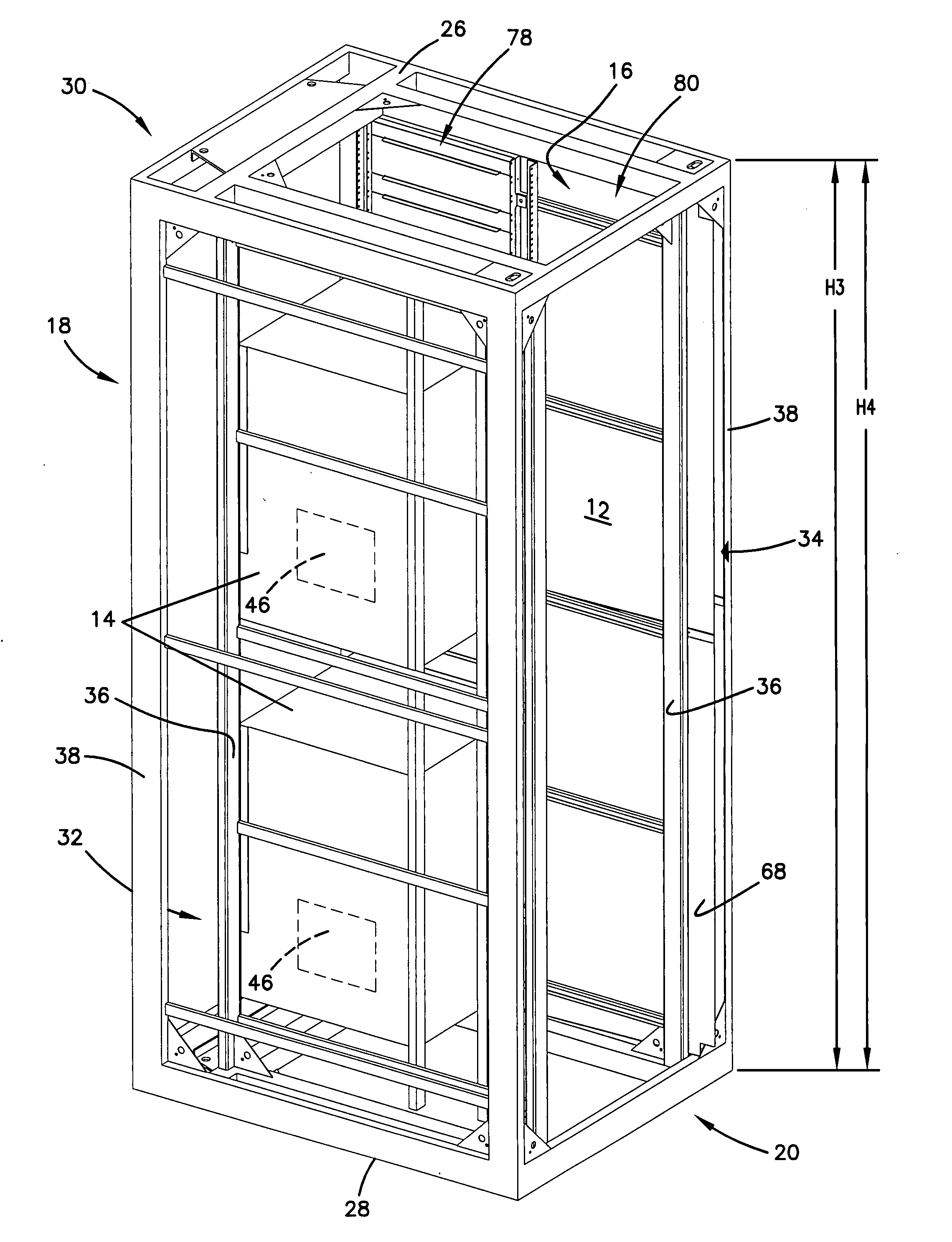
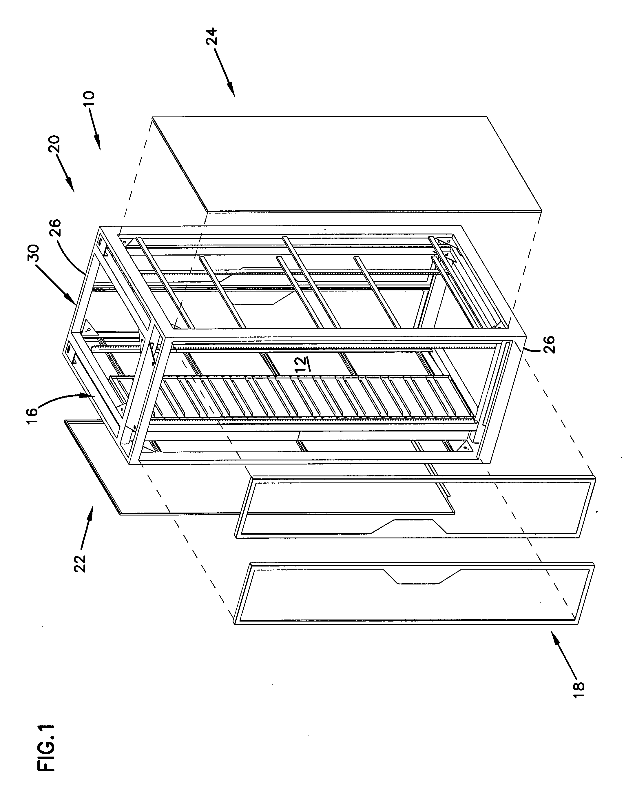
[0016]FIG. 1 illustrates one embodiment of a telecommunications cabinet 10 in accordance with the principles disclosed. The cabinet 10 generally has an interior 12 in which telecommunications equipment 14 (FIG. 3) is located. An airflow ducting arrangement 16 is also provided in the interior 12 of the cabinet 10. The ducting arrangement 16 facilitates airflow through the cabinet to aid in maintaining the thermal requirements of the telecommunications equipment.

[0017]While the present disclosure is directed toward a telecommunications cabinet, it is to be understood that features related to the airflow ducting arrangement can be utilized in other applications as well. For example, the disclosed thermal cooling features can be uti...


PUM

PropertyMeasurementUnit
Volumeaaaaaaaaaa
Heightaaaaaaaaaa

Abstract

A telecommunications cabinet in which active equipment can be mounted. The cabinet including an airflow ducting arrangement located in the interior region of the cabinet. The airflow ducting arrangement accommodating thermal cooling of active equipment having internal side-to-side air cooling arrangements.

Description

FIELD OF THE INVENTION[0001]This disclosure relates to equipment structures for use in the telecommunications industry, and associated methods. More specifically, this disclosure relates to a telecommunications cabinet that houses telecommunications equipment.BACKGROUND OF THE INVENTION[0002]Telecommunications equipment can generate a significant amount of heat and requires large volumes of air for cooling. Due to limited space in telecommunication facilities, telecommunications equipment is typically stacked within cabinets that are aligned side-by-side. Cabinets are typically enclosed by panels that generally protect the housed equipment.[0003]As can be understood, dissipation of heat generated by the equipment is critical to maintaining proper operation of the equipment. Yet, the side-by-side arrangement of cabinets and / or the enclosed construction of cabinets can impede the circulation of airflow necessary for thermal cooling. Side panels are often made of a solid construction, ...

Claims


Application Information

Patent Timeline
IPC IPC(8): H05K7/20
CPCH05K7/20572Y10T29/49826H04Q1/025H04Q1/035
Inventor HRUBY, KEVIN L.SCHOOK, NEALCORDLE, GLEN
Owner COMMSCOPE TECH LLC
Why Eureka
Try Eureka