Aircraft cabin lighting

Active Publication Date: 2008-10-30
THE BOEING CO
View PDF11 Cites 14 Cited by
  • Summary
  • Abstract
  • Description
  • Claims
  • Application Information

AI Technical Summary

Benefits of technology

[0006]The present embodiments provide a lighting configuration and scheme that changes or varies the a

Problems solved by technology

In general, the space in the passen

Method used


Image

  • Aircraft cabin lighting
  • Aircraft cabin lighting
  • Aircraft cabin lighting

Examples


Embodiment Construction

[0021]The disclosure now will be described more fully hereinafter with reference to the accompanying drawings, in which some, but not all embodiments are shown. The disclosure may be embodied in many different forms and should not be construed as limited to the embodiments set forth herein. Like numbers refer to like elements throughout.

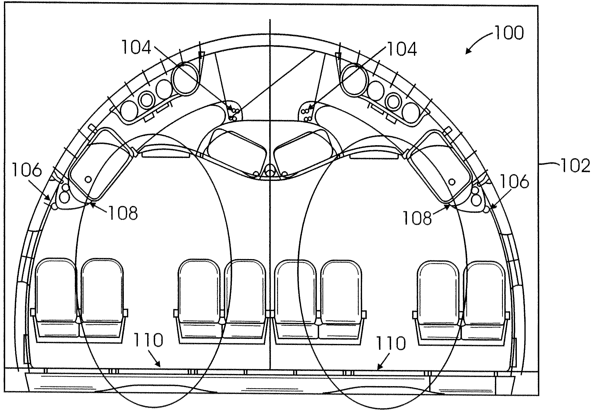
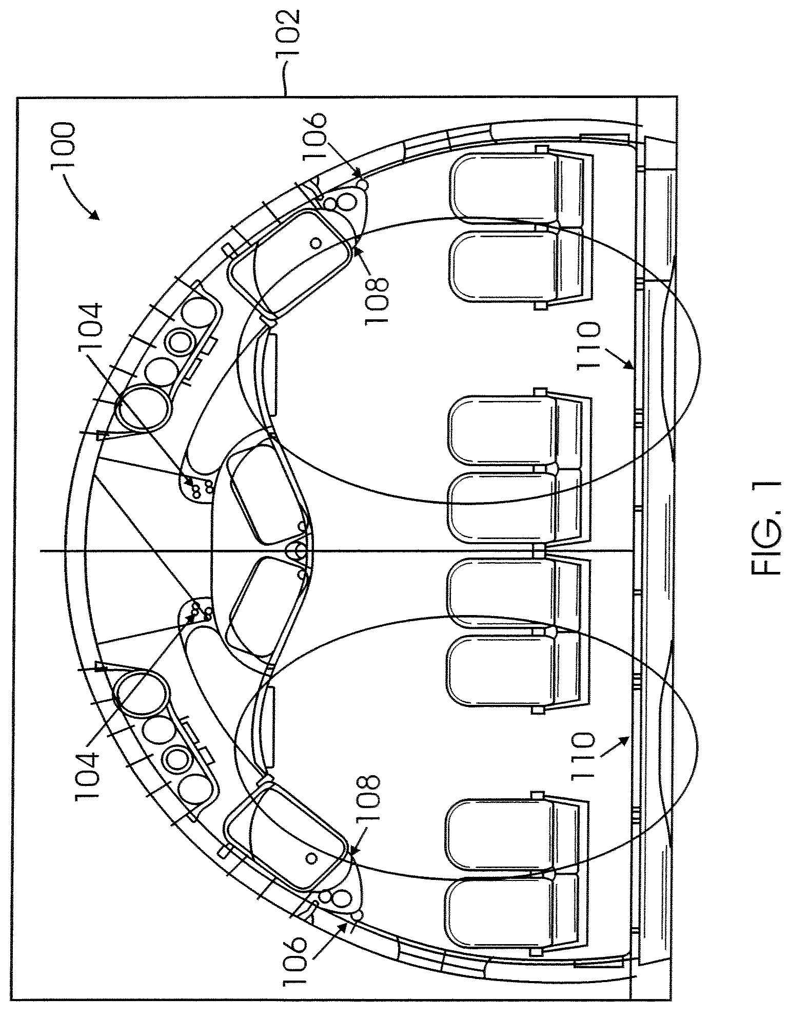
[0022]FIG. 1 is a simplified cross sectional view of an aircraft interior 100 showing a lighting scheme and configuration in accordance with an embodiment of the present disclosure. In one embodiment, the lighting scheme and lighting configuration (hereinafter “lighting system 102”) for aircraft interior 100 produces a two-tiered ceiling height effect by controlling the relative brightness levels of main ceiling lights 104, sidewall lighting 106, accent pot lights 108 and floor lights 110.

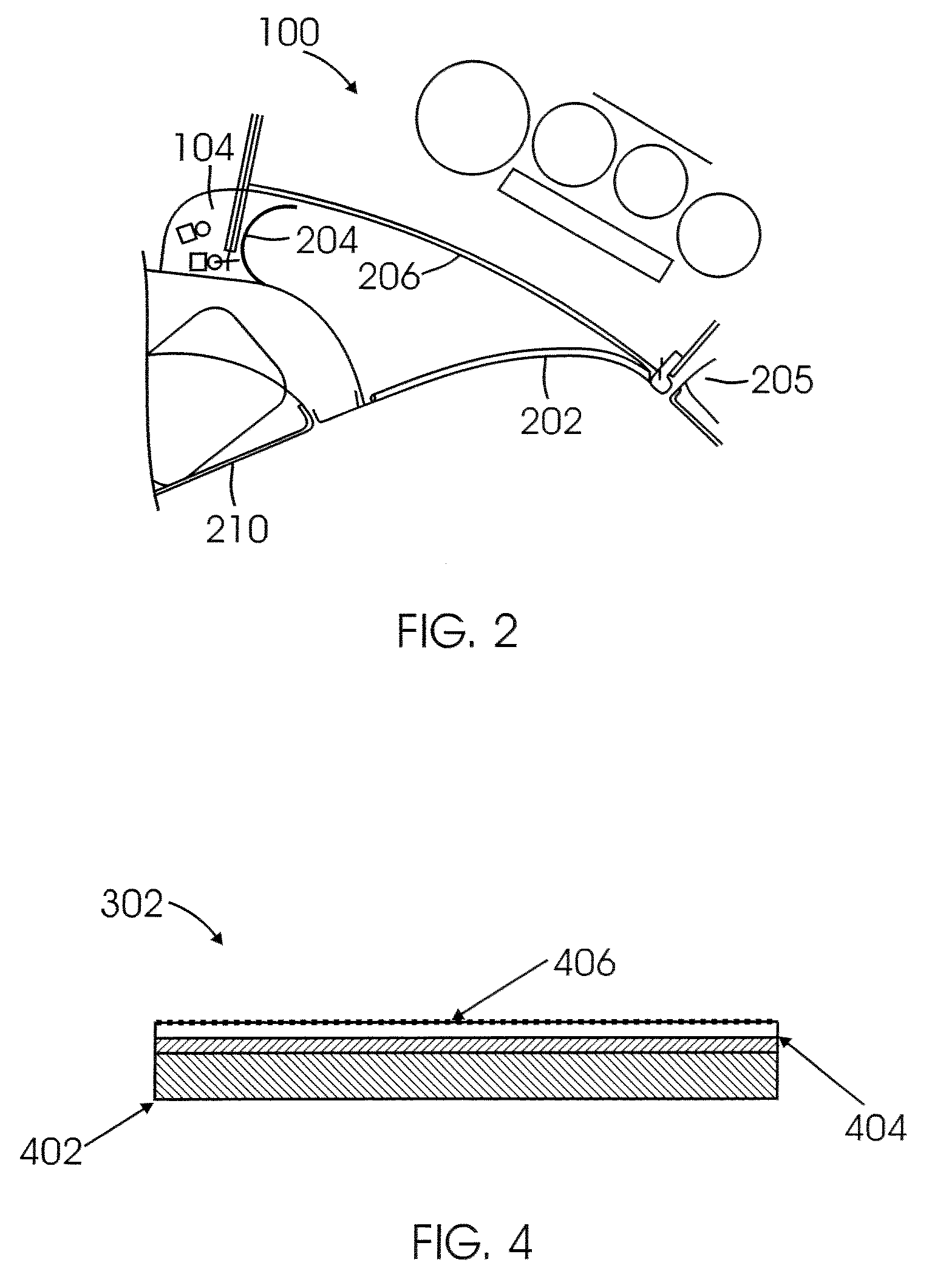
[0023]As shown in FIGS. 1, 2 and 3, in one embodiment the aircraft interior 100 includes ceiling panels and light diffusers. As shown in FIG. 2, ceiling panel membe...


PUM


Abstract

The incorporation of a variety of illumination sources to provide the additional light sources that reflect against a ceiling panel to provide an altered ceiling height effect in an aircraft. The incorporation of floor, aisle and door illumination provides the added benefit of facilitating emergency evacuation of the aircraft.

Description

CROSS-REFERENCE TO RELATED APPLICATIONS[0001]This application claims priority to provisional application Ser. No. 60 / 926,635, filed on Apr. 27, 2007, the entire contents of which are hereby incorporated by reference.BACKGROUND[0002]1. Technical Field[0003]The present disclosure relates generally to aircraft cabin lighting.[0004]2. Description of Related Art[0005]In general, the space in the passenger cabins of airplanes is limited. Therefore, there is a need in the aircraft industry for new and innovative solutions to passenger space limitations that provide all passengers with a feeling of utmost comfort.SUMMARY[0006]The present embodiments provide a lighting configuration and scheme that changes or varies the aesthetic appearance of passenger cabins in order to improve the perception of comfort within the space.[0007]The embodiments provide the lighting configuration and scheme to the passenger cabin to enhance the key rituals performed aboard the aircraft, such as boarding, resti...

Claims


Application Information

Patent Timeline
IPC IPC(8): B64D47/02
CPCB60Q3/025B60Q3/0259B64D11/00B64D47/02B64D2011/0038B60Q3/43B60Q3/47
Inventor WENTLAND, MARK E.LEBLANC, THOMAS L.LAU, CHARLES K.
Owner THE BOEING CO
Why Eureka
Try Eureka