
Sonic method and apparatus

Inactive Publication Date: 2006-09-28
MORROW CHARLES G
View PDF12 Cites 0 Cited by
  • Summary
  • Abstract
  • Description
  • Claims
  • Application Information

AI Technical Summary

Benefits of technology

[0014] The structure and method that characterize the invention also satisfies the need for a new approach to a sound reproduction technology that offers fresh artistic options for creating improved listener perceptions.
[0015] For instance, several parallelepiped arrays can be assembled, side by side, to produce even further impressive sonic effects. In a large gallery displaying a number of exhibits, this side-by-side arrangement of the transducer arrays can permit individual arrays to be activated without interfering with the sounds being generated in adjoining arrays

Problems solved by technology

Earlier efforts to create aural sensations that would exploit the potentials existing in the binaural nature of human hearing (the perception of sound with both cars) were not entirely satisfactory in their results.
All of these techniques—many of them quite elaborate in both the arrangement of the loud speakers and in the supporting electrical circuits—nevertheless failed to replicate nature.
This system still failed to provide a truly satisfactory binaural listener response.
For example, these prior art systems were not able to stimulate adequately the sensation of a moving sound source.
Thus, although the change in frequency as a moving sound source approached and then moved away from the listener, the Doppler Effect, could be projected through many of these systems, the systems still failed to create a perception of motion for the source of the sound relative to the listener.
As a general matter, it has not been possible to combine satisfactorily a system to establish a sound field that extends in all directions relative to the listener, an “ambisonic” system, with a system that generates a sound in which the source appeals to move relative to the listener, a “panned” system.
With respect to those systems that generate a sound field that extends in all directions relative to the listener, there is a further difficulty.
Consequently, listener movement and particularly head movement which is so fundamental to binaural sound stimulation, tends to degrade the perceived quality of the sound output.

Method used


Image

  • Sonic method and apparatus
  • Sonic method and apparatus
  • Sonic method and apparatus

Examples


Embodiment Construction

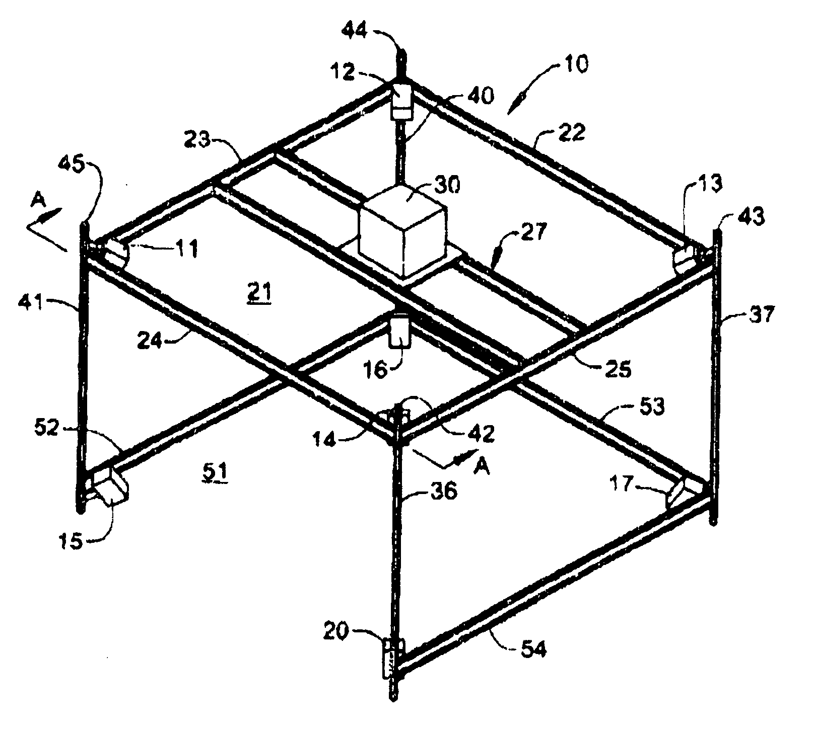
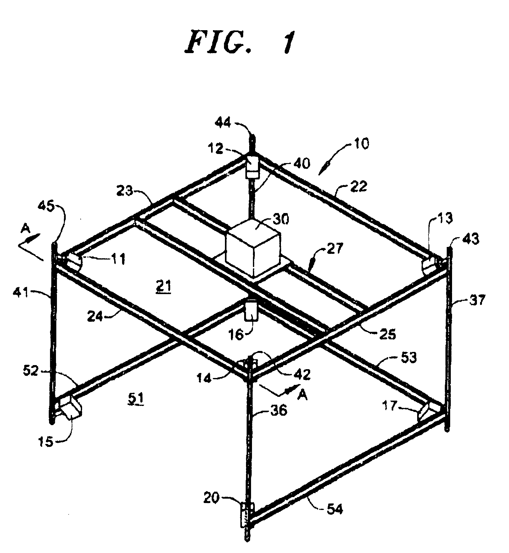
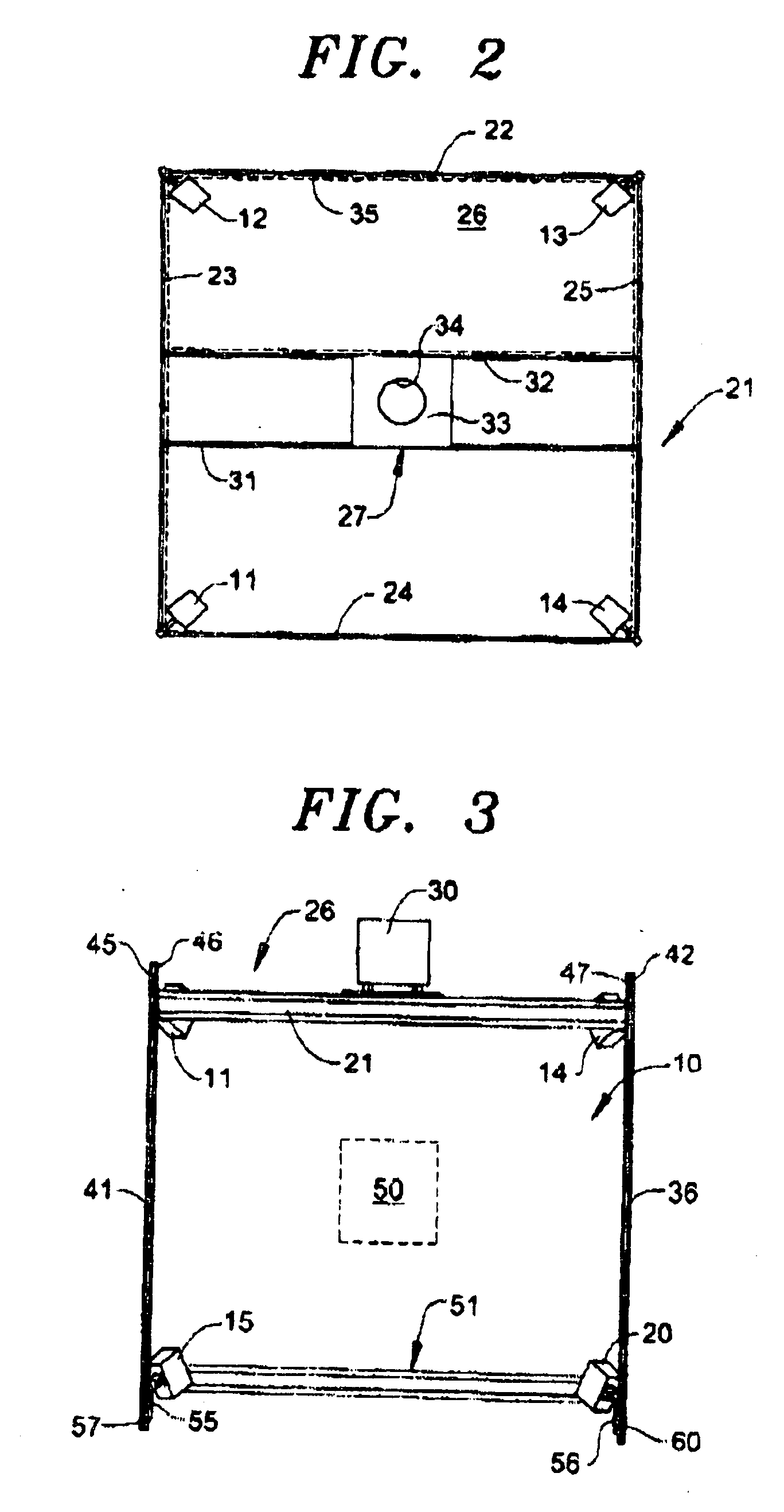
[0024] A specific embodiment of the invention is shown in FIG. 1. As illustrated, an array 10 of eight transducers 11, 12, 13, 14, 15, 16, 17 and 20 are spaced from each other to form a parallelepiped or, as shown in this embodiment of the invention, a cuboid 21. For the purpose of the embodiment Genelec 1029A sound transducers have been found to be satisfactory. Note in this respect that four of the sound transducers 11-14 are mounted in the manner subsequently described above the level of the listener's cars (not shown) and the sound transducers 15-17 and 20 are, mutatis mutandis, mounted below the listener's ear.

[0025] To provide the separation among the transducers the array 10 has a rectangular framework of structural members. Members, or cross beams 22, 23, 24 and 25 are joined together at their respective ends to form corners of a square, planar surface 26 (FIG. 2) for the cuboid 21. Suitable cross beams for this purpose are identified in the Octanorm Systems Catalog through...


PUM


Abstract

Full field sound and the perception of a moving sound source are combined by mounting an array of sound transducers. Some of the transducers are mounted above a listener's ear level and some of the transducers are mounted below the listener's ear level. The sounds generated by all of the transducers are oriented toward a common volume in which all of the generated sound intersects. A further sound transducer spaced from some of the other transducers also projects its generated sound into the common volume, thereby producing both a full field effect and the perception of a moving sound source.

Description

CROSS-REFERENCES TO RELATED APPLICATIONS [0001] None STATEMENT REGARDING FEDERALLY SPONSORED RESEARCH OR DEVELOPMENT [0002] None REFERENCE TO “SEQUENCE LISTING”[0003] None BACKGROUND OF THE INVENTION [0004] This invention relates to methods and apparatus for sound reproduction and more particularly to spatial arrays of sound transducers for creating an aural sensation that the sound source is moving relative to the listener, and the like. [0005] Earlier efforts to create aural sensations that would exploit the potentials existing in the binaural nature of human hearing (the perception of sound with both cars) were not entirely satisfactory in their results. These efforts did lead to some stereoscopic aural effects in an attempt to produce a perception of a more natural sound. All of these techniques—many of them quite elaborate in both the arrangement of the loud speakers and in the supporting electrical circuits—nevertheless failed to replicate nature. [0006] Illustrative of these ...

Claims


Application Information

Patent Timeline
IPC IPC(8): H04R5/02
CPCH04R1/025H04R5/02H04R2205/024H04S7/30
Inventor MORROW, CHARLES G.
Owner MORROW CHARLES G
Learn More