
Method and System for Ethernet Congestion Management

a congestion management and ethernet technology, applied in the field of communication networks, can solve the problems of congestion, traffic may require the best effort, and may occur when a device may receive more tcp, and achieve the effects of reducing the number of tcp

Inactive Publication Date: 2008-10-30
AVAGO TECH INT SALES PTE LTD
View PDF9 Cites 37 Cited by
  • Summary
  • Abstract
  • Description
  • Claims
  • Application Information

AI Technical Summary

Benefits of technology

The patent describes a way to manage congestion in Ethernet networks. This can help to prevent data from getting lost or being delayed in transmission. The patent outlines a system and method for managing this congestion, which can be useful for managing network traffic and ensuring reliable data transmission.

Problems solved by technology

The patent text discusses the challenges in managing network traffic and the need for efficient processing of different types of traffic. The technical problem addressed by the patent is the limited availability of buffer memory in networking devices, which can impact the performance and reliability of applications and protocols that use TCP. The patent proposes a solution to this problem by utilizing congestion management algorithms and offloading TCP/IP functionality to dedicated network processing hardware. Additionally, the patent discusses the challenges of integrating multiple types of network traffic over a single network and the need for separate management networks for different types of traffic. The patent also highlights the limitations of conventional approaches and proposes a solution to address these challenges.

Method used


Image

  • Method and System for Ethernet Congestion Management
  • Method and System for Ethernet Congestion Management
  • Method and System for Ethernet Congestion Management

Examples


Embodiment Construction

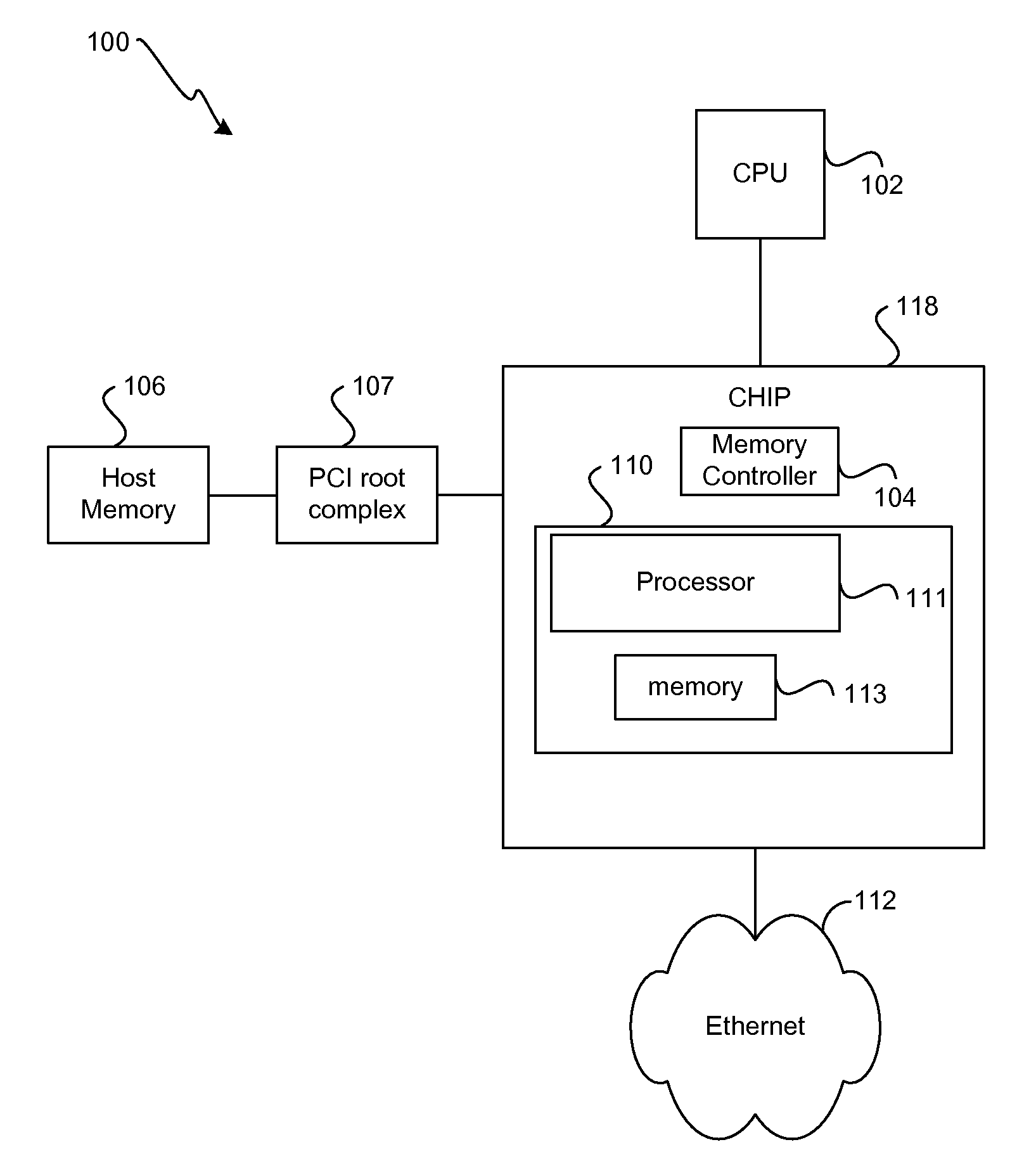
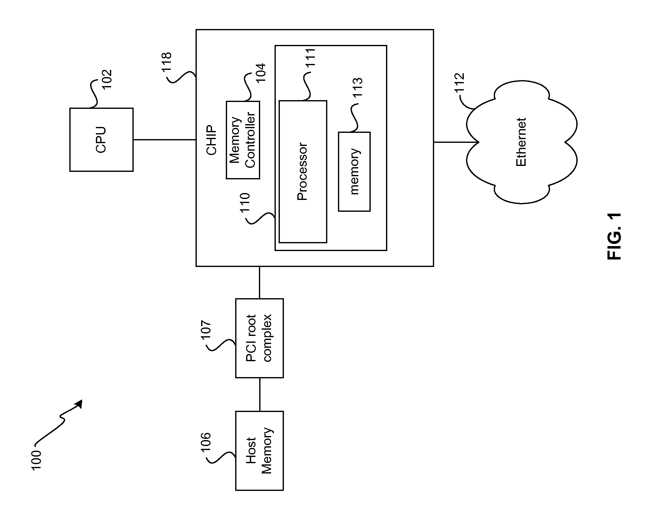
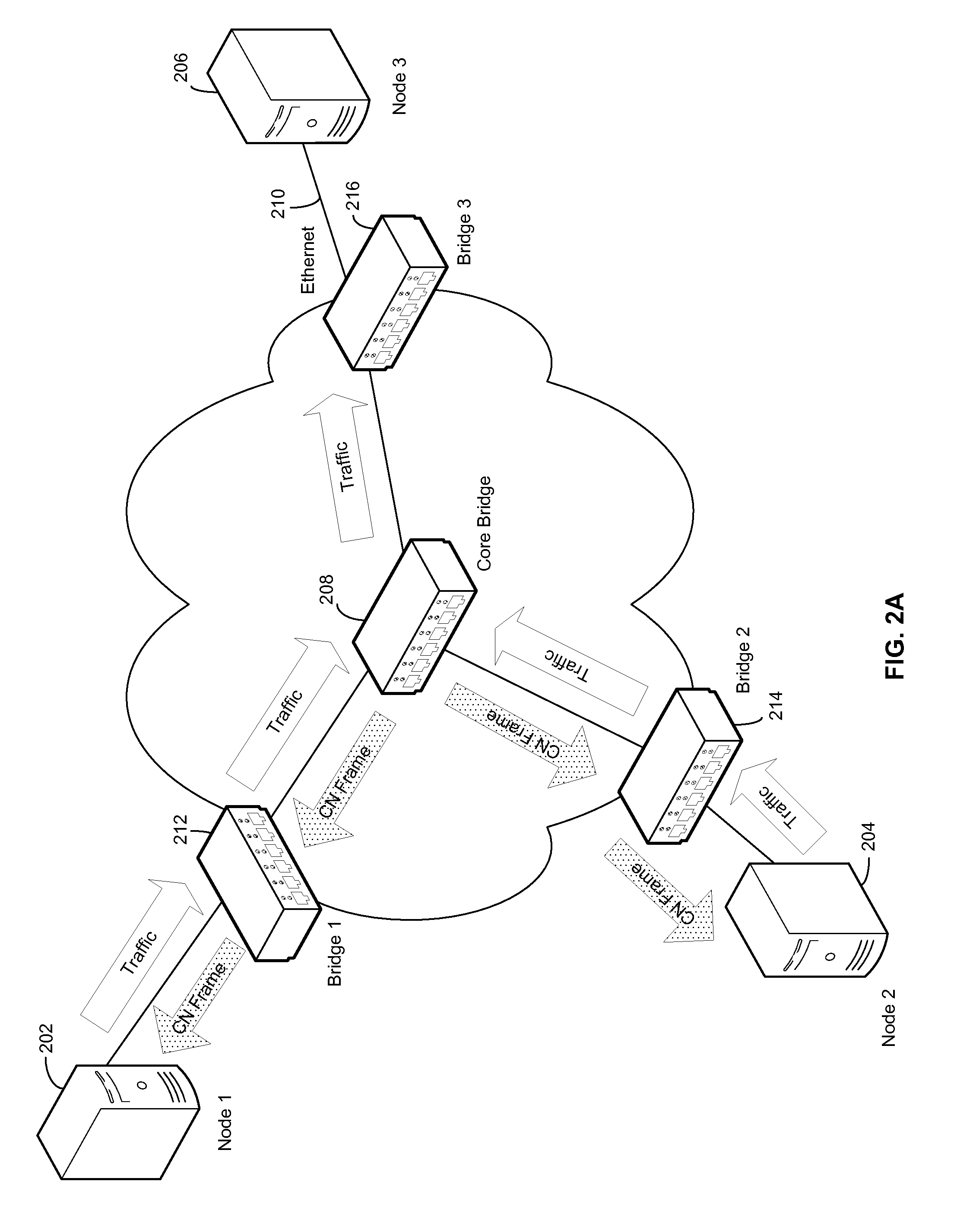
[0020]Certain embodiments of the invention may be found in a system and / or method for Ethernet congestion management. Exemplary aspects of the invention may comprise transmitting one or more data packets in a network flow from a source node to a destination node. The source node may be enabled to receive one or more congestion notification frames based on detecting congestion at one or more switches in the network flow. A probe packet comprising a departure timestamp, Ts, may be transmitted from the source node to the destination node based on receiving one or more congestion notification frames. The arrival rate, Ra, of one or more data packets at the destination node may be calculated based on an arrival timestamp, Ta, inserted into the probe packet at the destination node. A rate limiter at the source node may be enabled to limit a rate of one or more data packets based on the calculated arrival rate, Ra.

[0021]FIG. 1 is a block diagram of an exemplary system that may be utilized ...


PUM


Abstract

Certain aspects of a method and system for Ethernet congestion management may include transmitting one or more data packets in a network flow from a source node to a destination node. The source node may be enabled to receive one or more congestion notification frames based on detecting congestion at one or more switches in the network flow. A probe packet comprising a departure timestamp, Ts, may be transmitted from the source node to the destination node based on receiving one or more congestion notification frames. The arrival rate, Ra, of one or more data packets at the destination node may be calculated based on an arrival timestamp, Ta, inserted into the probe packet at the destination node. A rate limiter at the source node may be enabled to limit a rate of one or more data packets based on the calculated arrival rate, Ra.

Description


Claims


Application Information

Patent Timeline
Owner AVAGO TECH INT SALES PTE LTD
Learn More