Self-acting urethral valve

a urethral valve and self-acting technology, applied in the field of medical science, can solve the problems of insufficient difference between opening and closing pressure of the valve, difficult design of the reliable valve, and difficult removal of the valve, etc., and achieve the effect of convenient removal

Inactive Publication Date: 2008-10-30
WILKIE DAVID +1
View PDF0 Cites 25 Cited by
  • Summary
  • Abstract
  • Description
  • Claims
  • Application Information

AI Technical Summary

Problems solved by technology

Incontinence is a well known medical problem becoming more common as people age.
The problem is made more difficult by the low pressures involved.
Such low pressures can only supply very low forces inside the valve (a few grams) making the design of a reliable valve quite difficult.
U.S. Pat. Nos. 4,457,299; 4,553,533; 4,822,333; 5,888,188; 6,183,520; 6,027,442 and 6,652,448 disclose a self acting valves however this valve do not have a sufficient difference between the opening pressure and the closing pressure, therefore starts to close before the bladder is fully voided.
The fluid filled implementation disclosed in the '299 patent has even less desirable characteristics than a spring as the compression force required to collapse a sealed fluid filled enclosure goes up faster than linear.
U.S. Pat. Nos. 5,088,980; 5,437,604; 5,722,932 and 6,213,936 use the Bernoulli effect, a liquid filled bag or a compound valve system to create some differential between the opening pressure and the closing pressure but fail to meet the requirement for very large differential and unrestricted flow, as they create the differential by severely restricting the flow.
Clearly when urine pressure drops below 10 cm of water the voiding of the bladder will take a long time if the flow is very restricted, as flow rate drops with pressure.

Method used


Image

  • Self-acting urethral valve
  • Self-acting urethral valve
  • Self-acting urethral valve

Examples


Embodiment Construction

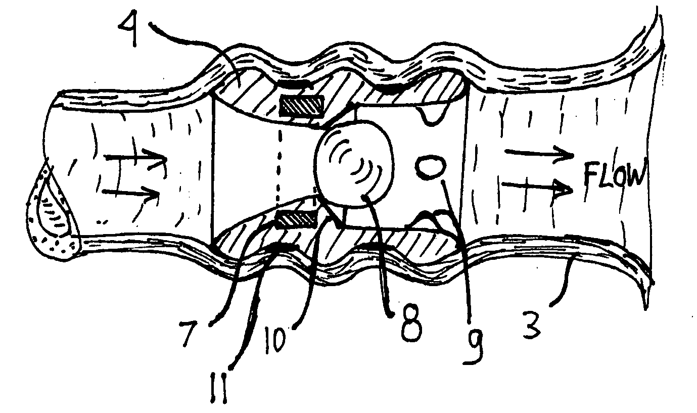
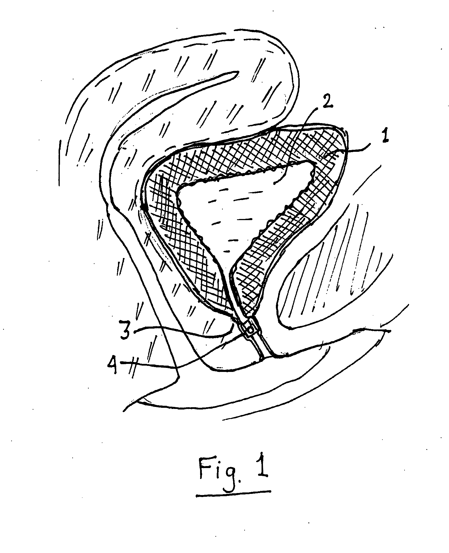
[0010]Referring to FIG. 1, valve 4 controls the flow of urine 2 from bladder 1 through urethra 3. A female anatomy is depicted but the invention is beneficial to both men and women.

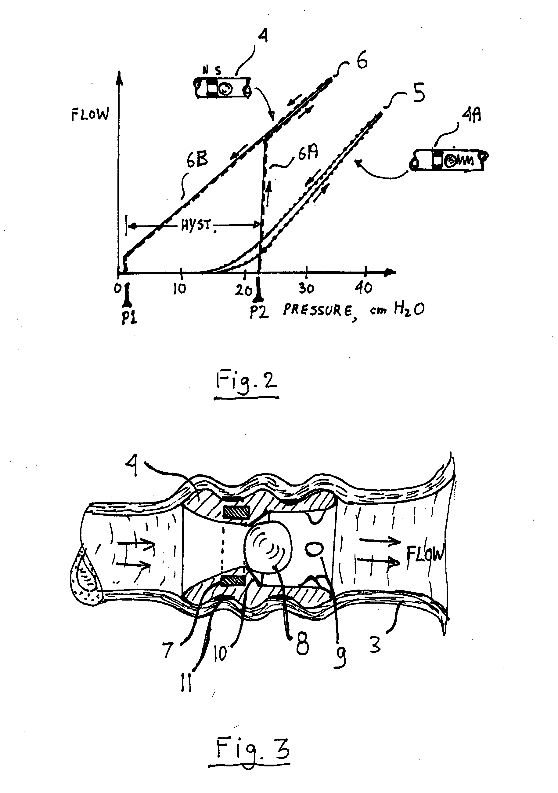
[0011]In order to emulate a correctly functioning urethra the valve needs to fully open at a set pressure and stay fully open, with as little flow restriction as possible, till bladder is empty and pressure drops to a small fraction of opening pressure. The pressure difference between the opening and closing pressure is also known as hysteresis. A simple spring loaded valve does not have the desired property. A spring provides little hysteresis, as can be seen in FIG. 2, showing flow as a function of bladder pressure. A spring loaded valve 4A will typically have a graph 5. When pressure reaches the opening point the valve opens slightly, and increased pressure increases the amount of valve opening and flow.

[0012]When pressure is reduced the graph generally traces back the increasing pressure graph. The de...


PUM


Abstract

The invention emulates the operation of a healthy urethra by providing a valve with a large differential between the opening pressure and the closing pressure. The differential is achieved by using a snap action created by the action of the urine flow on a force that drops off rapidly with displacement. A preferred way to achieve such as force is by using permanent magnets. The valve is installed simply by insertion into the urethra and can easily be removed. No surgical procedure is involved.

Description

FIELD OF THE INVENTION [0001]The invention is in the medical field, and specifically for the prevention of urinary incontinence in men and women.BACKGROUND OF THE INVENTION [0002]Incontinence is a well known medical problem becoming more common as people age. The majority of incontinence occurs in women, accelerated by anatomical changes following childbirth. Prior art treats incontinence by anatomical corrections done via minor surgery and by artificial urethral valves, restoring the ability of the urethra to act as a valve. In a healthy person the urethral muscles, acting together with the muscles contracting the bladder, are effective in achieving free flow when emptying the bladder and achieving a good seal against leakage at all other times. An ideal prosthetic urethral valve needs to open at a pre-determined point and provide as little obstruction to flow as possible. It should remain fully open as pressure drops, until bladder is completely emptied and pressure drops to a ver...

Claims


Application Information

Patent Timeline
Patent Type & Authority Applications(United States)
IPC IPC(8): A61F2/50
CPCA61F2/0022A61F2210/009
Inventor WILKIE, DAVIDGELBART, DANIEL
Owner WILKIE DAVID
Why Eureka
Try Eureka