Intermittent urinary catheter assembly and an adapter assembly for an intermittent urinary catheter

a technology of urinary catheter and adapter, which is applied in the field of intermittent catheters, can solve the problems that the existing products of intermittent urinary catheters have not provided a suitable solution

Active Publication Date: 2015-10-01
HOLLISTER INCORPORAED
View PDF14 Cites 17 Cited by
  • Summary
  • Abstract
  • Description
  • Claims
  • Application Information

AI Technical Summary

Benefits of technology

[0009]In one exemplary embodiment, a funnel is associated with the distal end of the catheter tube and defines the discharge opening wherein the urine discharge sleeve may have a first end secured to the funnel and a second, extendable end. Advantageously, the urine discharge sleeve may be concertina folded about the funnel, and a discharge funnel may be provided for extending the second end of the urine discharge sleeve. Alternatively, the urine discharge sleeve may be reverse folded and secured to the funnel utilizing a paper band, and a pull ring having an adhesive area may be secured to the second end of the urine discharge sleeve.
[0010]In another exemplary embodiment, a funnel is again associated with the distal end of the catheter tube and defines the discharge opening, but in this embodiment the urine discharge sleeve may have a first end secured to a fitting or nipple and a second, extendable end. The urine discharge sleeve may be concertina folded and disposed within a discharge funnel, or reverse folded and secured to the adapter by a paper band and, in the latter embodiment, a pull tab having an adhesive area thereon may suitably be secured to the

Problems solved by technology

However, this is not the case for some users such as those who are wheelchair bound who may encounter difficulty in being able to discharge urine from an intermittent urinary catheter directly into a toilet.
For wheelchair bound users who would otherwise be able to administer self-intermittent catheterization for voiding their bladder of

Method used


Image

  • Intermittent urinary catheter assembly and an adapter assembly for an intermittent urinary catheter
  • Intermittent urinary catheter assembly and an adapter assembly for an intermittent urinary catheter
  • Intermittent urinary catheter assembly and an adapter assembly for an intermittent urinary catheter

Examples


Embodiment Construction

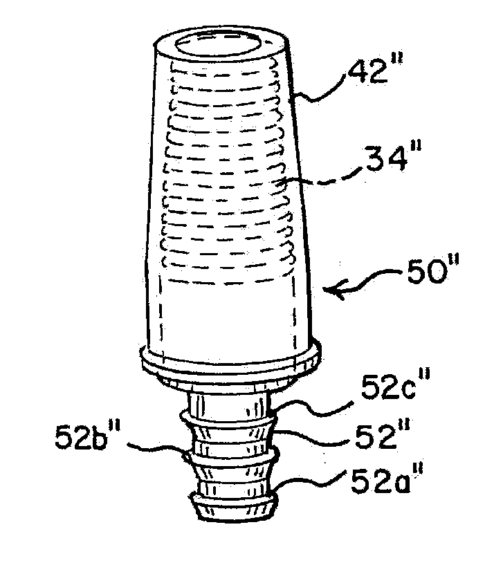
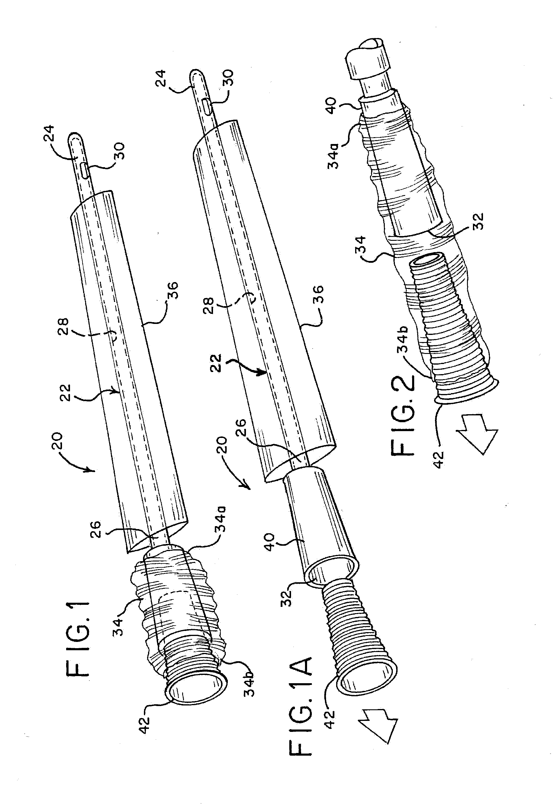
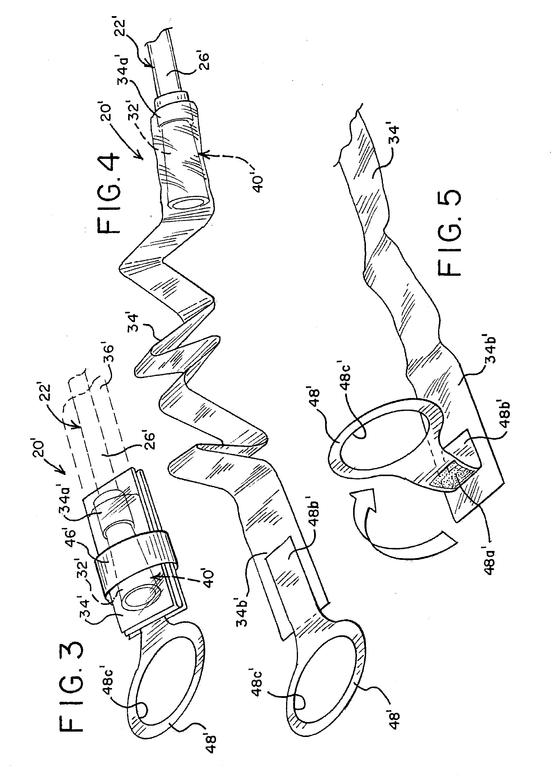
[0033]In the illustrations given, and with reference first to FIGS. 1, 1A and 2, the reference numeral 20 designates generally an intermittent urinary catheter assembly in accordance with the present disclosure. The intermittent urinary catheter assembly 20 will be seen to comprise a catheter tube 22 having a proximal insertion end 24 and a distal end 26 which is located remote from the proximal insertion end 24. The catheter tube 22 has a conventional lumen 28 which extends from at or near the proximal insertion end 24 to the distal end 26 to accommodate the draining of urine from a human bladder. The catheter tube 22 also has at least one drainage opening 30 which extends through the catheter tube 22 to the lumen 28 in a location at or near the proximal insertion end 24. The catheter tube 22 further has a discharge opening 32 (FIG. 1A) associated with the distal end 26 of the catheter tube 22 to permit urine voided from a human bladder to be discharged therefrom. The urine is disc...


PUM


Abstract

An intermittent urinary catheter assembly (20) comprises a catheter tube (22) having a proximal insertion end (24) and a distal end (26) remote from the proximal insertion end and a lumen (28) which extends from at or near the proximal insertion end to the distal end for draining urine from a human bladder. The intermittent urinary catheter assembly includes a urine discharge sleeve (34) associated with the discharge opening (30) of the catheter tube, and the urine discharge sleeve has a compact stowed configuration and is extendable into a deployed configuration for directing urine flow. Alternatively, an adapter assembly (50″) comprises a fitting or nipple (52″) having a urine passageway for insertion into a funnel (40″) associated with a urine discharge end of an intermittent urinary catheter, and a discharge funnel (42″) associated with the fitting or nipple, and an extendable urine discharge sleeve (34″) within the discharge funnel.

Description

RELATED APPLICATION[0001]This application claims the benefit of and priority to U.S. Provisional Patent Application Ser. No. 61 / 716,176, filed Oct. 19, 2012, the contents of which are incorporated by reference herein.FIELD OF THE DISCLOSURE[0002]The present disclosure is generally related to intermittent catheters for use in draining urine from the human bladder and, more particularly, to intermittent urinary catheter assemblies for use by those facing catheter drainage issues such as wheelchair bound users and the like.BACKGROUND OF THE DISCLOSURE[0003]Intermittent catheterization is a good option for many users who suffer from various abnormalities of the urinary system. A common situation is where a single use, individually packaged, sterile catheter is used. An important criterion for any single use product is that it be user friendly since there will often not be trained medical personnel performing catheterization.[0004]Due to the advancements that have been made in intermitte...

Claims


Application Information

Patent Timeline
IPC IPC(8): A61M25/00A61M39/10
CPCA61M25/0023A61M25/0021A61M39/10A61M25/0017A61M2039/1077A61M2025/0025A61M2210/1089A61M2210/1085A61M2025/0098
Inventor FOLEY, ADAM J.HENEGHAN, BRENDAN J.HANNON, DAVIDHENRY, JEROME A.MURRAY, MICHAEL G.
Owner HOLLISTER INCORPORAED
Why Eureka
Try Eureka