Side Branched Endoluminal Prostheses and Methods fo Delivery Thereof

a technology of endoluminal prostheses and side branches, applied in the field of endoluminal prostheses and methods of delivery thereof, can solve the problems of bifurcation, difficult placement and deployment of these prosthetic devices, and difficulty in achieving the effect of reducing the risk of surgical complications, and avoiding surgical complications

Active Publication Date: 2008-10-30
WL GORE & ASSOC INC
View PDF22 Cites 106 Cited by
  • Summary
  • Abstract
  • Description
  • Claims
  • Application Information

AI Technical Summary

Benefits of technology

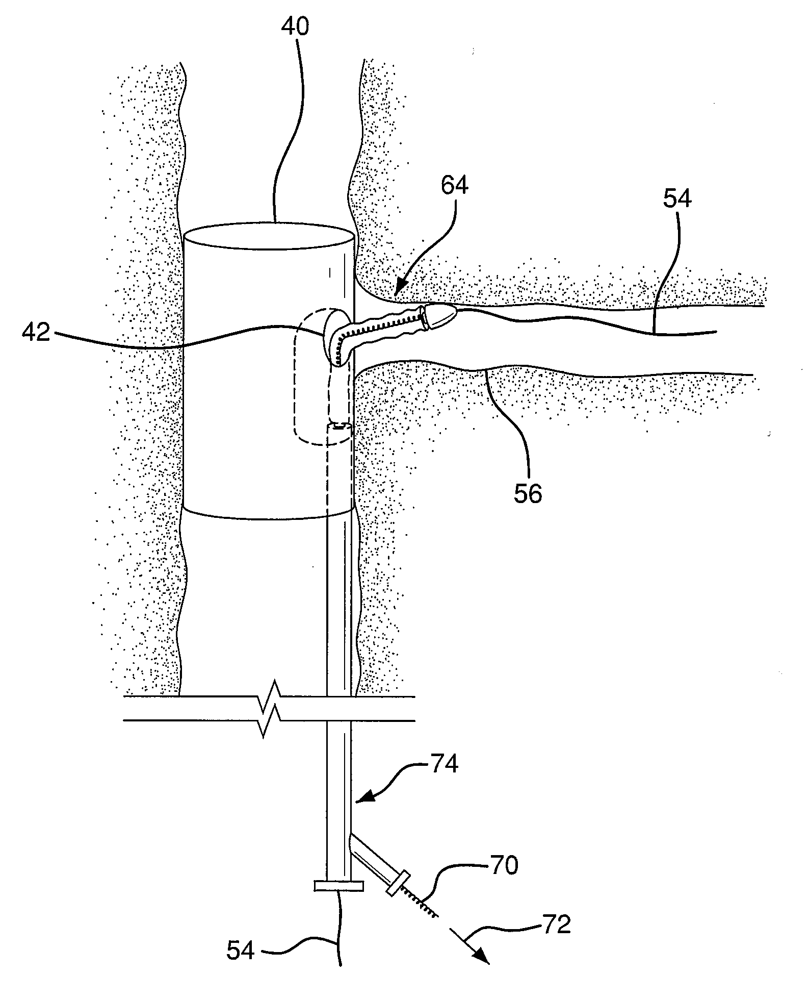
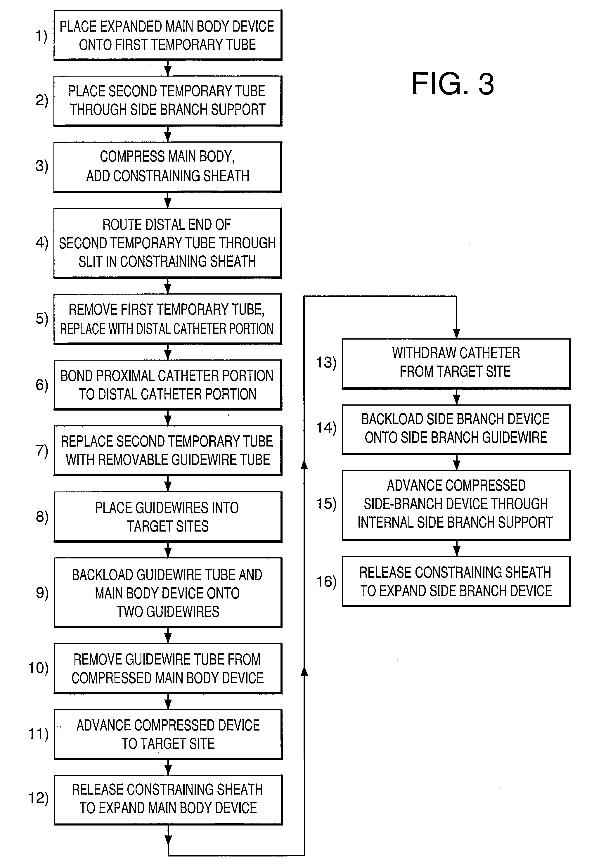
[0056]The catheter assembly can now be advanced to the target site. As shown in FIG. 11 the catheter and compressed main body device are advanced along the two guidewires 50, 54 until the sheath aperture 60 is aligned to the side branch vessel 56.
[0057]As shown in FIG. 12, the deployment cord 46 is pulled in the direction shown by arrow 62. By pulling on the deployment cord 46 the constraining sheath is split allowing the main body device 40 to self-expand and engage the main vessel 52. The constraining sheath (not shown) can be left in-vivo since the sheath will be captured between the main body stent and the main vessel lumen. The side branch guidewire remains routed through the main body side wall opening 42, through the internal side branch support 44 and out through the proximal end of the main body device.
[0058]The catheter 34 of FIG. 12 can now be removed, leaving the expanded main body device 40 and the side branch guidewire 54 in place.
[0059]A compressed side branch stent graft can then be back loaded onto the side branch guidewire. As shown in FIG. 13, the side branch guidewire 54 can be ins...

Problems solved by technology

Placement and deployment of these prosthetic devices at bifurcations can often be problematic.
Procedural complications are often encountered while practicing this technique.
Subsequent placement of the side branch guidewire through the main body pros...

Method used


Image

  • Side Branched Endoluminal Prostheses and Methods fo Delivery Thereof
  • Side Branched Endoluminal Prostheses and Methods fo Delivery Thereof
  • Side Branched Endoluminal Prostheses and Methods fo Delivery Thereof

Examples


example 1

[0063]An expandable prosthetic device having a removable guidewire tube can be fabricated as follows:

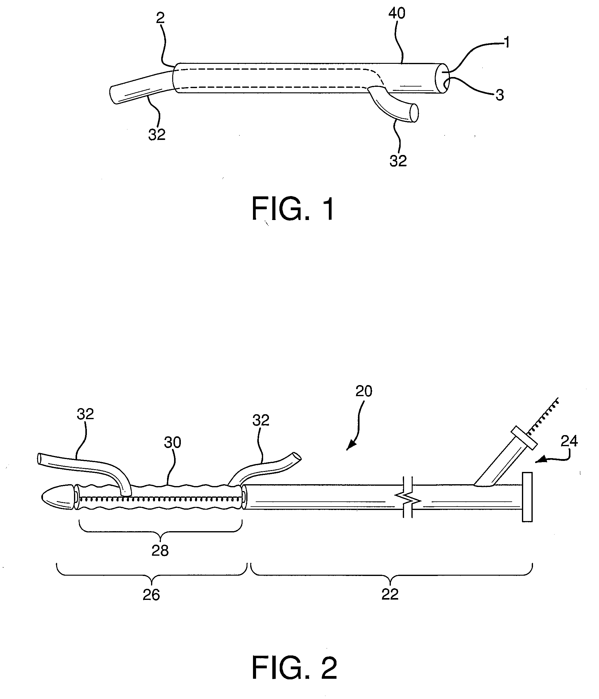
[0064]1) A self-expanding, main body stent graft can be provided having an outer diameter of 3.1 cm, a length of 15 cm and a graft wall thickness of about 0.005″. The graft material can comprise ePTFE and FEP and be formed from an extruded and expanded thin walled tube that is subsequently wrapped with ePTFE film. A nitinol wire having a diameter of about 0.0165″ can be helically wound to form a stent having an undulating, sinusoidal pattern. The formed, heat-treated stent can be placed onto the base graft. An additional film layer of ePTFE and FEP can be wrapped onto the stent and base graft to selectively adhere the stent to the graft.

[0065]2) The main body stent graft can have an internal side-branch support channel formed into the graft wall. Details relating to exemplary fabrication and materials used for an internal side branch support channel can be found in U.S. Pat. No. 6,64...


PUM

PropertyMeasurementUnit
Translucencyaaaaaaaaaa

Abstract

An expandable prosthetic device and method of delivery that allows the initial placement of multiple guidewires into selected target sites. The prosthesis includes a main body device. This main body device has a separate side branch guidewire lumen that passes through the main body device and through a side opening in the main body device. As the main body device is advanced, the side opening is self guided (by the side branch guidewire) and self-aligns to the side branch vessel ostium. The main body device is then deployed, leaving the side branch guidewire in place. A side branch device is then advanced along the side branch guidewire through the main body device, through the side wall opening and into the native side branch vessel. The side branch device can then be deployed to engage the main body device and the native side branch vessel.

Description

FIELD OF THE INVENTION[0001]The present invention relates to endoluminal prostheses and methods of delivery thereof. The endoluminal prostheses and method of delivery are particularly suited for use in bifurcated regions of body lumens.BACKGROUND OF THE INVENTION[0002]Stents or stent grafts are examples of expandable endoluminal prosthetic devices which are used to maintain, open or dilate stenotic lesions in body lumens or to cover and repair an aneurysm. Vascular disease may occur at a branch or bifurcation in a vessel. Placement and deployment of these prosthetic devices at bifurcations can often be problematic. One current technique is to initially deploy across an aneurysm, a main body prosthetic device having a side wall opening. The side wall opening is aligned with the side branch ostium. A second prosthetic device is then deployed through the main body prosthetic device side wall opening and into the side branch vessel. Procedural complications are often encountered while p...

Claims


Application Information

Patent Timeline
IPC IPC(8): A61F2/06
CPCA61F2/07A61F2/856A61F2002/075A61F2/966A61F2002/061A61F2/958A61F2210/0004A61F2210/0014A61F2230/0006A61F2250/006A61F2002/9623A61F2/95A61F2/97A61F2002/9511A61F2/954A61F2002/826A61F2/9522
Inventor HAMER, ROCHELLE M.JOHNSON, ERIC GERARD
Owner WL GORE & ASSOC INC
Why Eureka
Try Eureka