Method and an Apparatus for Decoding an Audio Signal

a technology of audio signal and decoding method, applied in the field of methods and decoding audio signals, can solve the problems of inability to control the gain and panning of individual object signals, and the bandwidth of the apparatus and method for decoding multi-object signals is large, so as to improve the disadvantages of the related art

Inactive Publication Date: 2008-10-30
LG ELECTRONICS INC
View PDF20 Cites 56 Cited by
  • Summary
  • Abstract
  • Description
  • Claims
  • Application Information

AI Technical Summary

Benefits of technology

[0013]Another object of the present invention is to provide a method and an apparatus for decoding an audio signal, comprising a downmix signal and a combined object parameter to be made in a MCU combiner, to control object gain and output in a teleconference or other application.

Problems solved by technology

But when multi-channel audio signals having only multi-channel parameters are used in the MCU, the MCU only can control the gain and panning of one of the channels and cannot control the gain and panning of individual object signals.
However, an apparatus and method for decoding multi-object signals needs a wide bandwidth.

Method used


Image

  • Method and an Apparatus for Decoding an Audio Signal
  • Method and an Apparatus for Decoding an Audio Signal
  • Method and an Apparatus for Decoding an Audio Signal

Examples


Embodiment Construction

[0025]Reference will now be made in detail to the preferred embodiment of the present invention, examples of which are illustrated in the accompanying drawings. Wherever possible, the same reference numbers will be used throughout the drawings to refer to the same or like parts.

[0026]Prior to describing the present invention, it should be noted that most terms disclosed in the present invention correspond to general terms well known in the art, but some terms have been selected by the application as necessary and will hereinafter be disclosed in the following description of the present invention. Therefore, it is preferable that the terms defined by the applicant be understood on the basis of their meanings in the present invention.

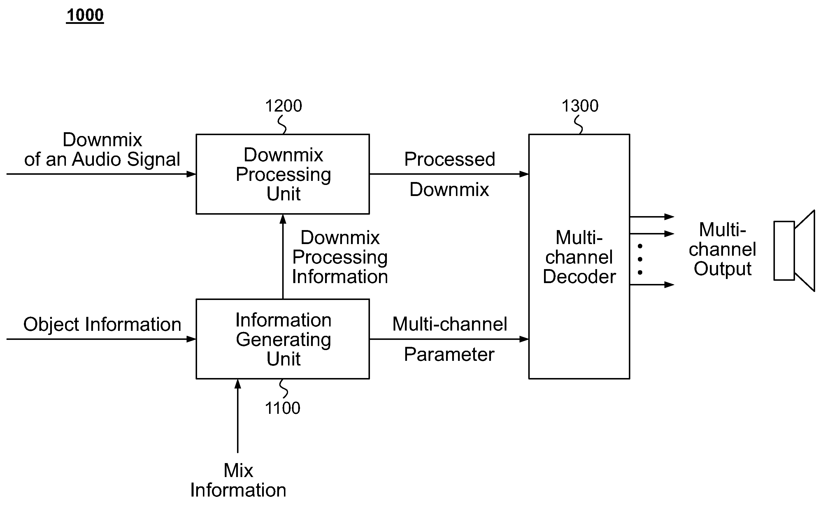
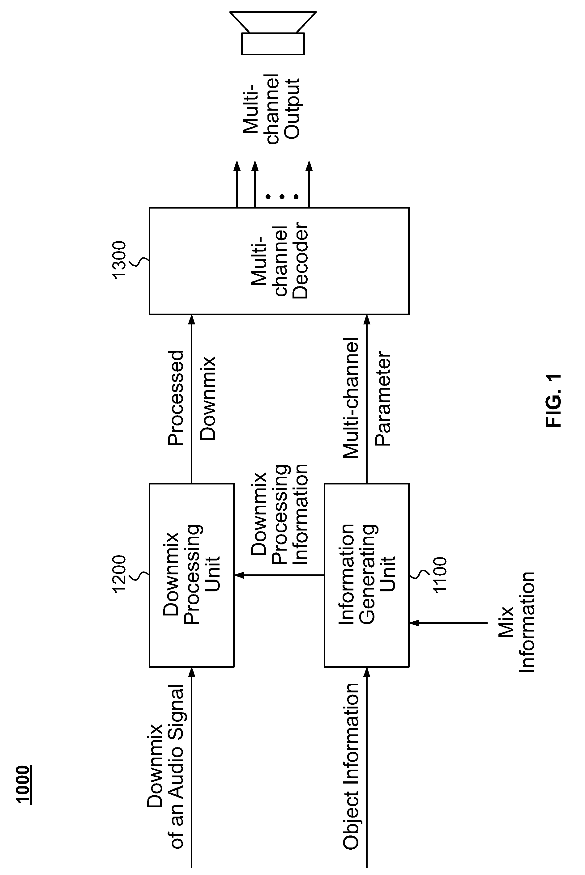
[0027]FIG. 1 is an exemplary block diagram of an apparatus 1000 for decoding an audio signal according to one embodiment of the present invention. FIG. 3 is an exemplary block diagram of an apparatus 2000 for decoding an audio signal according to another ...


PUM


Abstract

A method of decoding for an audio signal comprises the step of receiving a downmix of an audio signal, an object information, and a mix information, the object information including an object level information, an object correlation information, and an object gain information, generating a downmix processing information using the object information and the mix information, and processing the downmix of the audio signal using the downmix processing information. Various embodiments of the present invention provide a method and an apparatus for decoding multi-object audio signals fast and efficiently by reducing process time, computer resource, thereby relieving the resource requirement like the wide bandwidth. The object parameters according to the embodiments of the present invention can provide backward compatibility in the view of the channel-oriented decoding process.

Description

RELATED APPLICATIONS[0001]This application claims the benefit of U.S. Provisional Patent Application Nos. 60 / 865,908, 60 / 869,007, 60 / 869,080, 60 / 889,715, 60 / 955,395, and 60 / 883, 567, filed on Nov. 15, 2006, Dec. 7, 2006, Dec. 7, 2006, Feb. 13, 2007, Aug. 13, 2007, and Jan. 5, 2007, respectively, each of which is hereby incorporated by reference.BACKGROUND[0002]1. Field of the Invention[0003]The present invention relates to a method and an apparatus for decoding an audio signal, and more particularly, to a method and an apparatus for decoding an audio signal received via various digital medium.[0004]2. Discussion of the Related Art[0005]While downmixing several audio objects to a mono or a stereo audio signal, information (e.g., parameters) from individual object signals of the audio signal can be extracted. This information can be used in a decoder for decoding of the audio signal.[0006]A MCU (Multipoint Control Unit) is a device that can be used in a teleconference to articulate pr...

Claims


Application Information

Patent Timeline
Patent Type & Authority Applications(United States)
IPC IPC(8): G06F17/00
CPCG10L19/008G10L19/20
Inventor OH, HYEN-OJUNG, YANG-WON
Owner LG ELECTRONICS INC
Why Eureka
Try Eureka