Swivel device for monitor

a monitor and swivel technology, applied in the direction of instruments, furniture parts, electrical apparatus casings/cabinets/drawers, etc., can solve the problems of poor inability to adjust slip torque, and insufficient design, so as to improve the yield on the production line and solve the problem of market complaints

Inactive Publication Date: 2008-11-06
SHIMONISHI GIKEN KOGYO KK
View PDF7 Cites 13 Cited by
  • Summary
  • Abstract
  • Description
  • Claims
  • Application Information

AI Technical Summary

Benefits of technology

[0006]1) Since the slip torque can be adjusted even after assembling, th

Problems solved by technology

A conventional swivel device for monitor was not designed to adjust the operating force when rotating and manipulating the monitor manually in horizontal direction, that is, the slip torque could not be adjusted.
Since the slip torque could not be adjusted

Method used


Image

  • Swivel device for monitor
  • Swivel device for monitor
  • Swivel device for monitor

Examples


Embodiment Construction

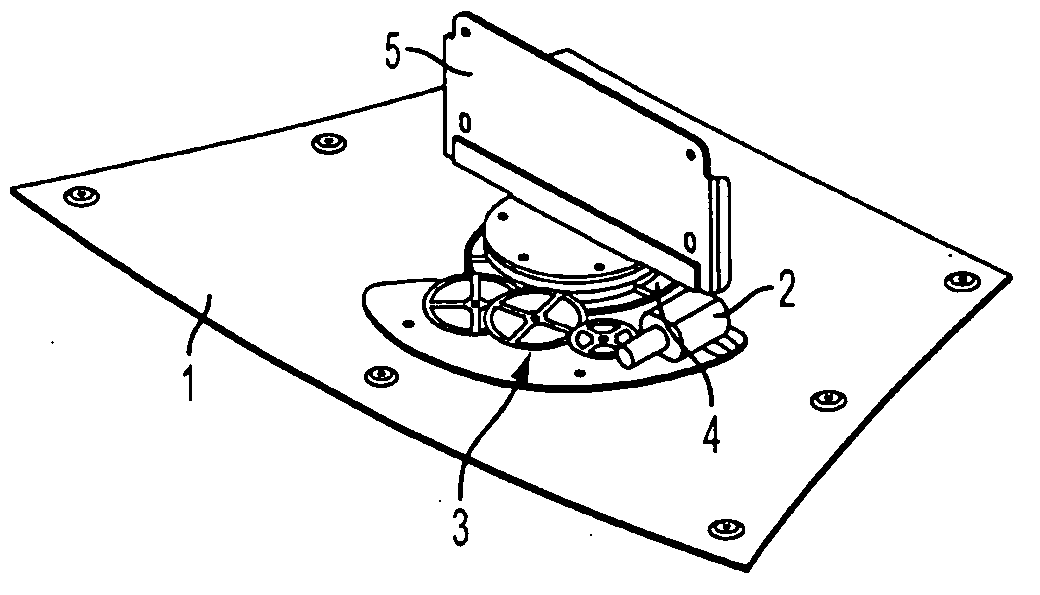
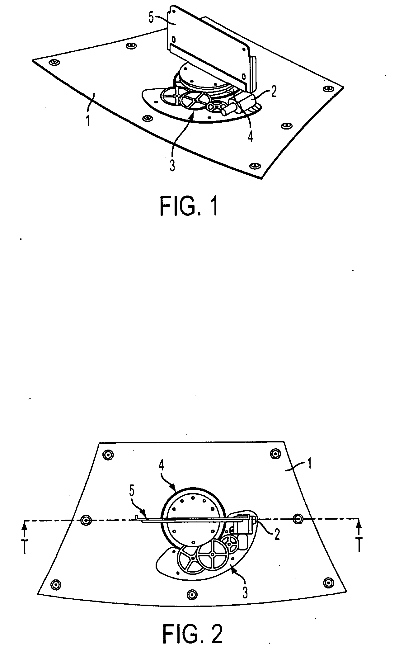
[0008]FIG. 1 is a perspective view of an embodiment of a swivel device for monitor of the invention, and FIG. 2 is its plan view, in which reference numeral 1 is a base plate, 2 is an electric motor, 3 is a reduction gear train, 4 is an output gear, and 5 is a monitor mounting plate.

[0009]The base plate 1 may be mounted on a proper monitor platform (not shown), or may be replaced by the platform. The output gear 4 is rotated and driven by an electric motor 2 by way of a reduction gear train 3. A proper monitor (not shown) is mounted on the monitor mounting plate 5.

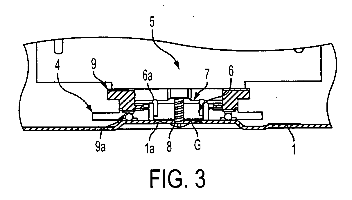
[0010]FIG. 3 is a sectional magnified view along line A-A in FIG. 2, in which reference numeral 6 is a fixing bench for slip torque adjusting plate, 7 is a slip torque adjusting plate, 8 is an adjusting screw, and 9 is a clutch plate.

[0011]The fixing bench 6 for slip torque adjusting plate is coaxially inserted in a hole formed in the center of rotation of the output gear 4, and is fixed by a pin la projecting from the bas...


PUM


Abstract

[Problem] To present a swivel device for monitor capable of adjusting the swivel operating force even after assembling, that is, adjusting the slip torque, by solving the problems in the prior art.
[Solution] The structure includes a base plate, an output gear disposed rotatably on the base plate and rotated and driven by an electric motor, a clutch plate rotated and driven while frictionally contacting with the output gear by way of a slip portion, a monitor mounting plate mounted and fixed on the clutch plate, and means for adjusting the contact frictional force of the clutch plate on the output gear.

Description

TECHNICAL FIELD [0001]The present invention relates to a swivel device for monitor for changing the direction of a monitor screen of a television monitor or the like laterally.TECHNICAL BACKGROUND [0002]A conventional swivel device for monitor was not designed to adjust the operating force when rotating and manipulating the monitor manually in horizontal direction, that is, the slip torque could not be adjusted.[0003]Since the slip torque could not be adjusted after assembling, the yield was poor on the production line, and market complaints could not be solved, and an optimum operating force must be adjusted individually according to each television size and its weight, and a manual swivel device was demanded.DISCLOSURE OF THE INVENTION Problem to be Solved by the Invention[0004]It is hence an object of the invention to present a swivel device for monitor capable of adjusting the swivel operating force even after assembling, that is, adjusting the slip torque, by solving the proble...

Claims


Application Information

Patent Timeline
IPC IPC(8): F16M11/00
CPCF16M11/08F16M11/18F16M2200/08
Inventor KATSUMATA, TSUTOMUUEMURA, YASUYUKI
Owner SHIMONISHI GIKEN KOGYO KK
Why Eureka
Try Eureka