Affixing pin for dry wall or the like

a technology of dry wall or similar, applied in the field of adhesive pins, can solve the problems of ineffective use of circular thread pins, high manufacture cost, and limited modification

Inactive Publication Date: 2008-11-06
LIEN CHIN HSIUNG
View PDF7 Cites 1 Cited by
  • Summary
  • Abstract
  • Description
  • Claims
  • Application Information

AI Technical Summary

Benefits of technology

[0015]a penetrating pin, which is adapted for penetrating through the dry wall, having a sharp pin end, a controlling tail, a peripheral surface extended from the pin end to the controlling tail, and a force distributing surface which is integrally extended from the peripheral surface and is extended from the pin end towards the controlling tail, wherein the force distributing surface of the penetrating pin is adapted for minimizing a damage force against materials of the dry wall while the penetrating pin penetrating therethrough, such that when a pushing force is applied at the controlling tail for inserting the pin end of the penetrating pin into a wall surface of the dry wall to form a hole thereon, the force distributing surface is guided for sliding at a surrounding surface of the hole to minimize said pushing force to penetrate the penetrating pin through the dry wall.

Problems solved by technology

However, most of the modifications are limited to the pusher handle part for allowing an easier or more convenient grab for the user to perform the pushing and twisting action.
The problem with such modification is that the manufacture cost is high and it is not too effective to use circular thread pins that have really short pin body.
Also the circular threads inevitably add additional damage as the pin head is inserting through the dry wall thus allowing more space for the pin head to become loose while inside the dry wall and eventually starts to slide out and fail its function.
Another existing problem of such conventional affixing is that the pivot point is not strong enough for support if the affixing pin is hanging heavy materials thus creating a strong moment that might damage the dry wall or even make the pin head and body to slip out from the wall.
Another disadvantage of such conventional affixing pins is that it is allowed to rotate freely once the affixing pin is inserted into the dry wall.
Under this situation, the hanging affixing pin can slide out of the dry wall hole and fail the hanging objective.

Method used


Image

  • Affixing pin for dry wall or the like
  • Affixing pin for dry wall or the like
  • Affixing pin for dry wall or the like

Examples


Embodiment Construction

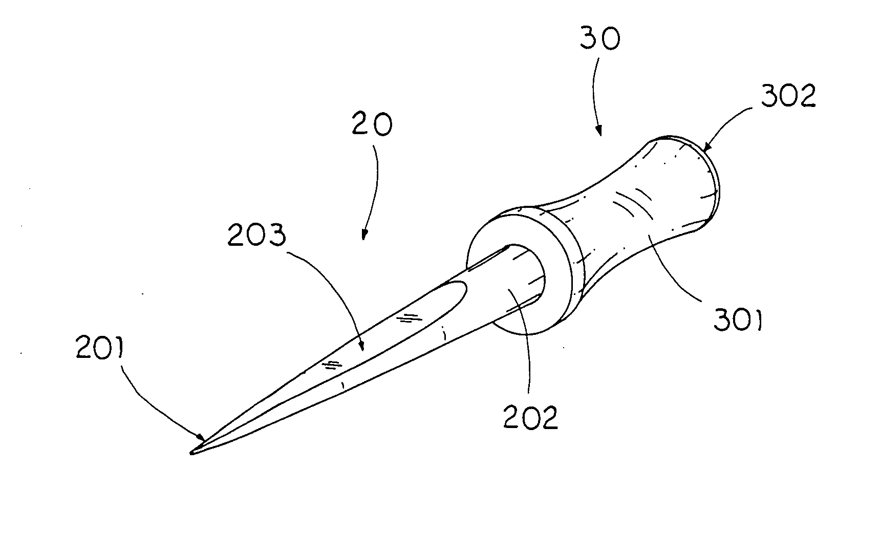
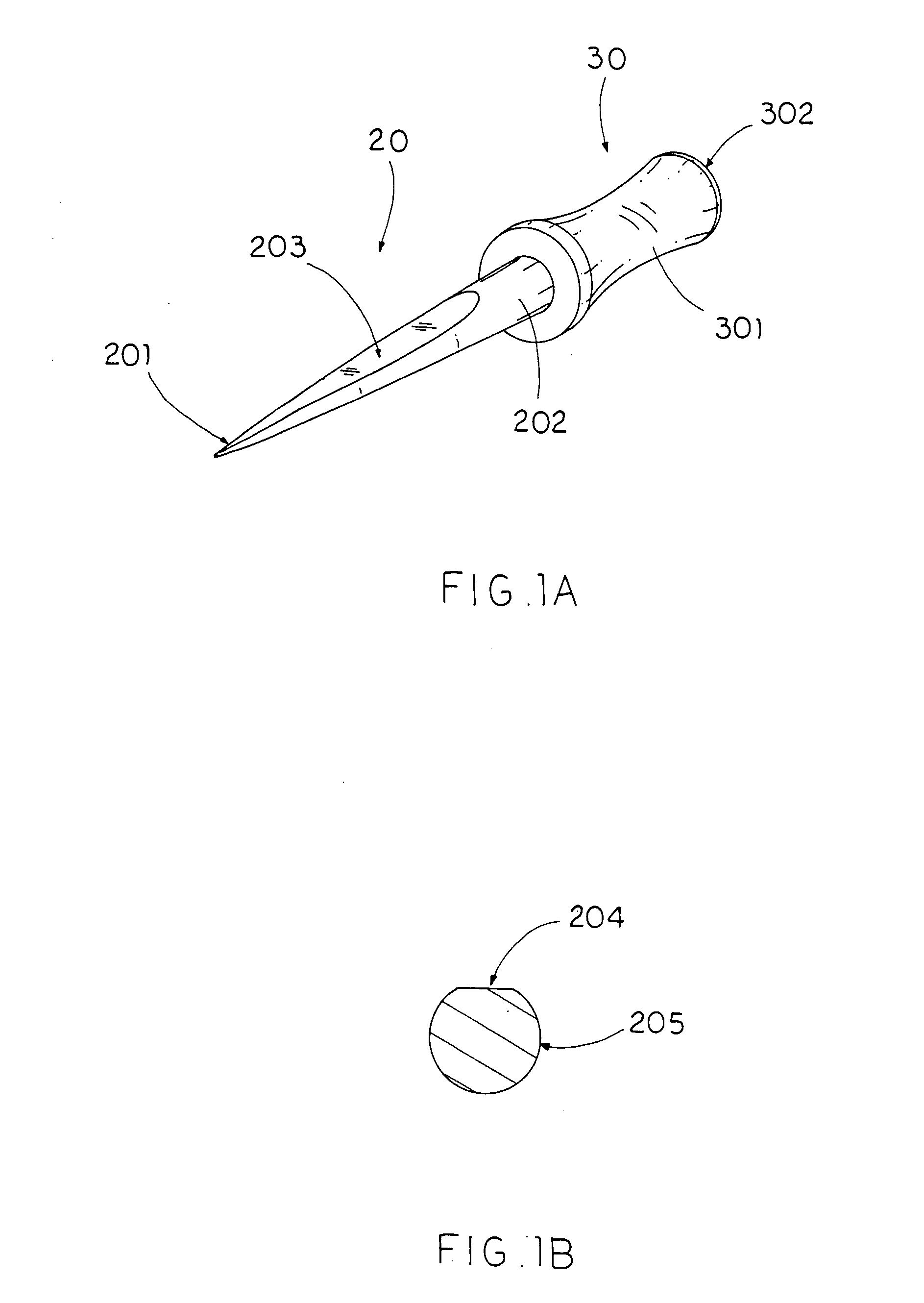
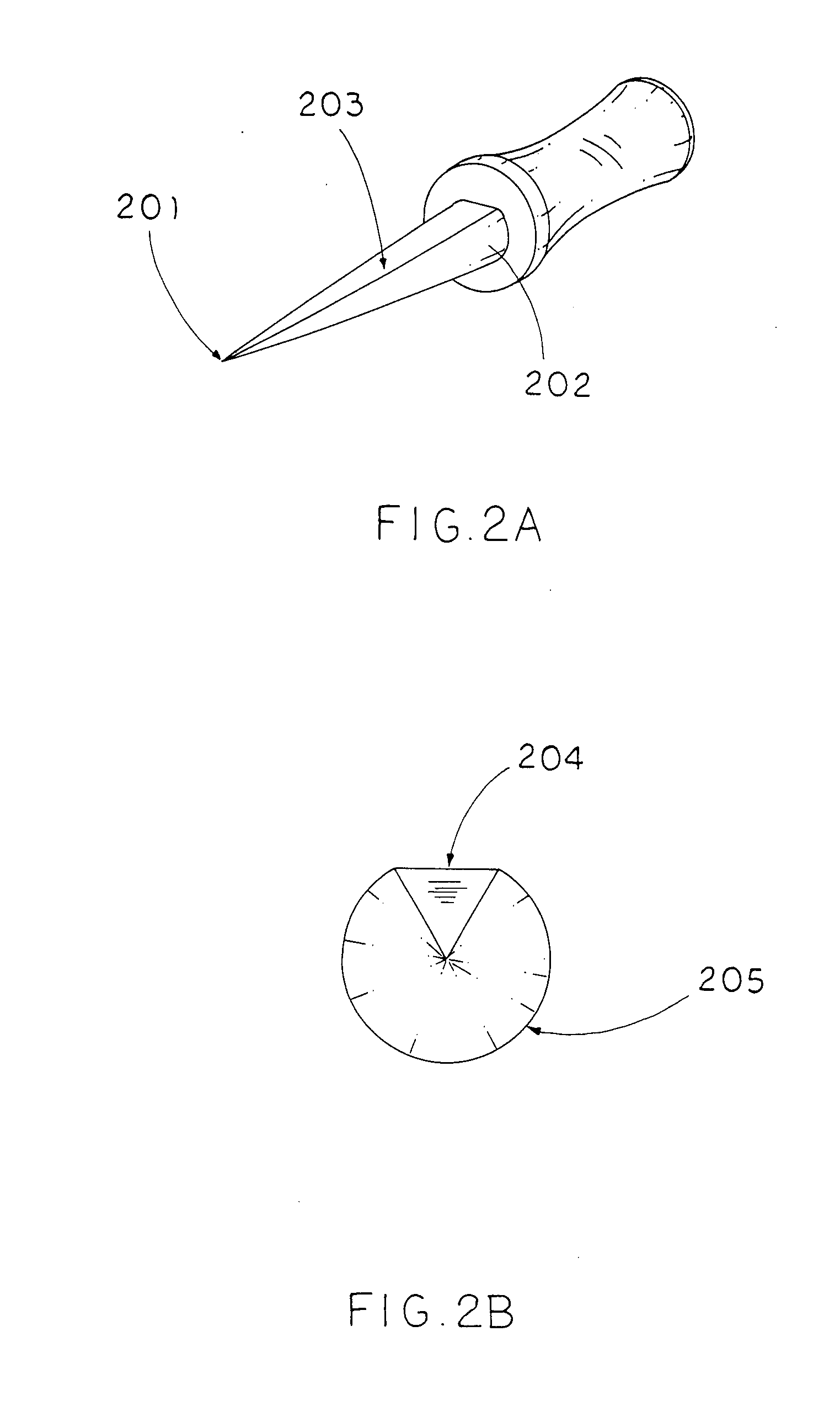
[0025]Referring to FIG. 1a of the drawings, an affixing pin comprises a penetrating pin 20 and a pusher head 30 couples to an end of the penetrating pin 20. The penetrating pin 20 further comprises a penetrating tip 201 which is designed to have a sharp tip for penetrating through object like dry wall, a controlling tail 202 which determines a penetrating direction of the penetrating pin 20, and a force distributing surface 203 extending coaxially along from the penetrating tip 201 towards the controlling tail 202.

[0026]The pusher head 30, which couples with the controlling tail 202 coaxially, further comprises a grip handle 301 and a flat pushing surface 302 disposed at an end thereof as well. The grip handle 301 and the flat pushing surface 302 are both typically in cylinder shape and the diameter of the grip handle 301 is smaller than the diameter of the flat pushing surface 302, thus leaving a cavity surrounding the grip handle 301 to allow users to place their fingers therewith...


PUM


Abstract

A dry wall affixing pin, having a penetrating pin which has a penetrating tip for penetrating through a dry wall, a controlling tail coupling with the penetrating tip for determining a penetrating direction of the penetrating pin, and a force distributing surface which extends from the penetrating tip towards the controlling tail. The dry wall affixing pin also has a pusher head coupling with the controlling tail which has a grip handle and a flat pushing surface disposed at an end thereof for user to conveniently push the affixing pin into the dry wall. The force distributing surface further has a flat and peripheral surface for minimizing a contact force against materials from the dry wall while penetrating through.

Description

BACKGROUND OF THE PRESENT INVENTION[0001]1. Field of Invention[0002]The present invention relates to an affixing pin, and more particularly to an affixing pin for inserting into a dry wall and allowing the user to do so easily without applying as much pushing force as the conventional affixing pin requires.[0003]2. Description of Related Arts[0004]The conventional affixing pin for dry wall or the like, as shown in FIG. 1, comprises a sharp inserting head, a pin body, and a pusher handle. The sharp head is provided at a tip end of the pin body for conveniently inserting through objects such as a dry wall. It is generally extended rearwardly and conically with an increasing diameter towards the pusher handle which usually is as elongated uniform cylinder shape. The sharp tip end allows the inserting head to insert into the dry wall surface then, under a tip end pushing action, the inserting head pushes the dry wall material radially to create a hole in the dry wall for the affixing pi...

Claims


Application Information

Patent Timeline
Patent Type & Authority Applications(United States)
IPC IPC(8): F16B15/00
CPCF16B15/00
Inventor LIEN, CHIN-HSIUNG
Owner LIEN CHIN HSIUNG
Why Eureka
Try Eureka