Method for plowing ground with a plough device comprising two cutting elements

a technology of cutting elements and ploughing equipment, which is applied in soil-working methods, agricultural tools and machines, and soil-replenishing methods. it can solve the problems of high tractive force, particularly significant subprocessing effort, and high force required for holding the plow in the ploughing direction, so as to reduce the need for tractive force and reduce the need for plows. the effect of plows

Active Publication Date: 2022-09-29
HUBER SOIL SOLUTION GMBH
View PDF13 Cites 0 Cited by
  • Summary
  • Abstract
  • Description
  • Claims
  • Application Information

AI Technical Summary

Benefits of technology

[0014]A substantial advantage of the invention is that the friction and shearing forces, i.e. the soil reaction forces, of the method using the plow device moving through the ground can be minimized. A method for plowing ground is thus provided which ensures a lower tractive force requirement and, associated therewith, a significant fuel saving. In addition, further advantages consist in the fact that improved ecological agricultural ground tillage is possible, because the ground can be better loosened and aerated, and can thus be better supplied with oxygen in the sense of CO2-exchange. In addition, damaging plow pan formation can be prevented, and the number of tillage operations until the seedbed is prepared can be reduced. The present invention proceeds from the fundamental consideration that, in the case of a conventional plow, the plowshare scrapes through the ground horizontally, as it were, and an earth ridge is cut out of the ground perpendicularly by means of a disc colter and a moldboard edge. Owing to the curvature of the plowshare, the earth ridge that forms the furrow is subsequently transferred to an adjacent moldboard which receives the ridge, winds it into a helical shape, and subsequently deposits it to the side, at a turn angle of approximately 130°. Owing to the relatively high friction forces, the tractive forces during plowing are also relatively high. The present invention begins to overcome these disadvantages of conventional method for plowing ground using rigid plow bodies having rigid components in that novel, rotatable machine elements are used which perform the plowing itself. In principle, the rotating cutting elements have a positive effect on the tractive force requirement. According to the invention, this has been achieved in that just two cutting tools, which interact in a synergistic manner, represent the actual plow structure, the tractive force requirement when pulling the plow through the ground being significantly reduced, in comparison with rigid plow elements, simply by the fact that said cutting tools are rotating cutting elements.
[0015]According to the invention, a method for plowing ground is proposed, said method comprising the following method steps: A support structure is moved on the ground in a plowing direction to be performed, which movement is followed by first cutting element (concave disc) of a side region of an earth ridge of the ground, for which purpose a first cutting region of a first cutting edge of a first cutting element is provided, which is arranged on the support structure. Two angles (cutting or direction angle and hitch or inclination angle) of the first cutting element, defined in the plowing direction, is preferably adjusted mechanically or hydraulically or electrically, preferably continuously. It is thus possible to vary the force conditions and plowing results, taking account of different ground qualities and usage conditions. Furthermore, a base region of an earth ridge of the ground is cut by means of a second cutting region of a second cutting edge of a second cutting element, which is likewise arranged on the support
[0016]The second cutting region of the second cutting element being used for cutting the earth ridge furrow base is in front of the first cutting region of the first cutting element in the plowing direction. A work angle or clearance angle α of the second cutting element, defined in the plowing direction, is preferably continuously adjusted mechanically or hydraulically or electrically. It is thus possible to vary the hold down force conditions and plowing results, taking account of different ground qualities and usage conditions. The clearance angle α also prevents smearing effects on the furrow base.
[0017]It is noted that, in order to simplify understanding, the terms “horizontal” and “vertical” and “upper” and “lower” relate to arrangements and embodiments of the plow devices, the plow device being considered to be resting as intended on the ground and movable in the tillage direction during plowing operation.
[0018]The inventive method is preferably implemented by a plow device for plowing ground which comprises a support structure, a rotatable cutting element (e.g. a toothed disc), and a second cutting element (e.g. a further toothed disc that is angled relative to the first cutting element). The rotatable first cutting element comprises a circumferential first cutting edge, the first cutting element being arranged on the support structure and being designed such that a side region of an earth ridge of the ground (in particular of a furrow wall of the ground) can be cut by means of a first cutting region of the first cutting edge when the support structure is moved on the ground in a plowing direction (i.e. the tillage direction). The second cutting element comprises a second cutting edge, the second cutting element being arranged on the support structure and being designed such that a base region of an earth ridge of the ground (in particular along a separation plane between the earth ridge and the plow sole) can be cut by means of a second cutting region of the second cutting edge when the support structure is moved on the ground in the plowing direction. The second cutting element is arranged relative to the first cutting element, in the plowing direction, such that the second cutting region is arranged in front of the first cutting region, in the plowing direction.
[0019]The novel method is being implemented by a plow comprising two discoid or plate-shaped cutting tools. In this case, one cutting tool is designed such that it divides the lateral edges of an earth ridge from the continuous ground by means of a cut, whereas the second cutting element separates the earth ridge from the continuous earth, at the plowing depth, in the region of the furrow base. The first cutting element that is intended for a substantially vertical cutting plane is preferably designed as an annular plate, specifically similarly to the disc colters, the annular plate comprising a circumferential cutting edge as the rotatable, substantially vertical cutting element. The circumferential cutting edge is preferably curved and thus vertically cuts out the earth ridge that has been horizontally pre-cut in the region of the furrow base and has been detached from the plowed-up topsoil in the furrow base region, and allows the cut-out earth ridge to pass through the concave hollow region of the annular plate and to slide back, in a turned form, from the annular plate and into the furrow. In this case, the annular plate comprises various depressions and elevations in the form of different radii, such as what are known as basket arches, i.e. inside planar surfaces followed by different radii or just one radius overall, which can be adapted accordingly, depending on the ground conditions. The geometry and the diameter of the annular plate have a significant influence on the result of the plowing process. The fact that the annular plate, i.e. a curved disc, is preferably toothed at the cutting edge results in improved engagement in the ground. The annular plate is preferably attached to the support structure by means of a plurality of adjustable machine elements in such a way that the work angle is variable. The cutting elements are preferably attached to the support structure so as to be exchangeable.

Problems solved by technology

This subprocess requires a particularly significant tractive effort in the case of a moldboard plow.
Furthermore, a high force is required for holding the plow in the plowing direction, since high lateral forces act on the plow as a result of the removal of the earth ridge.
This results in the earth ridges that have been removed from the ground and turned being present on the field in a compacted state.
When a ground tillage machine of this kind has to be pulled through the ground, the circumferential loosening devices of the subsoil loosening device result in a relatively high tractive force and a relatively high drive power requirement for the subsoil loosening device loosening device, which are disadvantageous because said high tractive forces can be applied only by more powerful machines, and, in addition, this results in relatively high fuel consumption.
Irrespective thereof, the ground enrichment that is intended to be achieved using the subsoiler is in part compensated again in that heavy machines result in greater ground compaction on the field.
Since the plow body that is arranged in front of the annular plate penetrates into uncut earth, this also requires a relatively high tractive force, which likewise involves the disadvantages described above.
An earth ridge cannot be created, lifted, or even turned using a plow device of this kind.

Method used


Image

  • Method for plowing ground with a plough device comprising two cutting elements
  • Method for plowing ground with a plough device comprising two cutting elements
  • Method for plowing ground with a plough device comprising two cutting elements

Examples


Embodiment Construction

[0116]The same or similar components in different figures are provided with the same reference signs. The drawings in the figures are schematic.

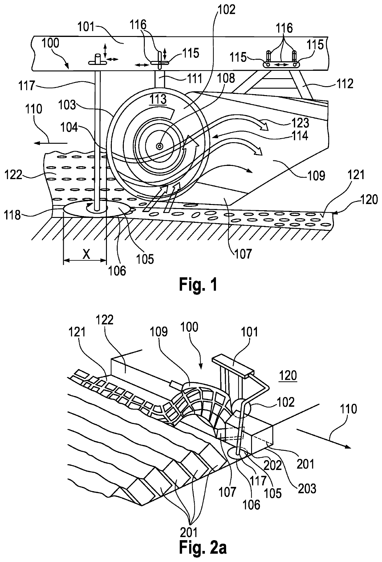
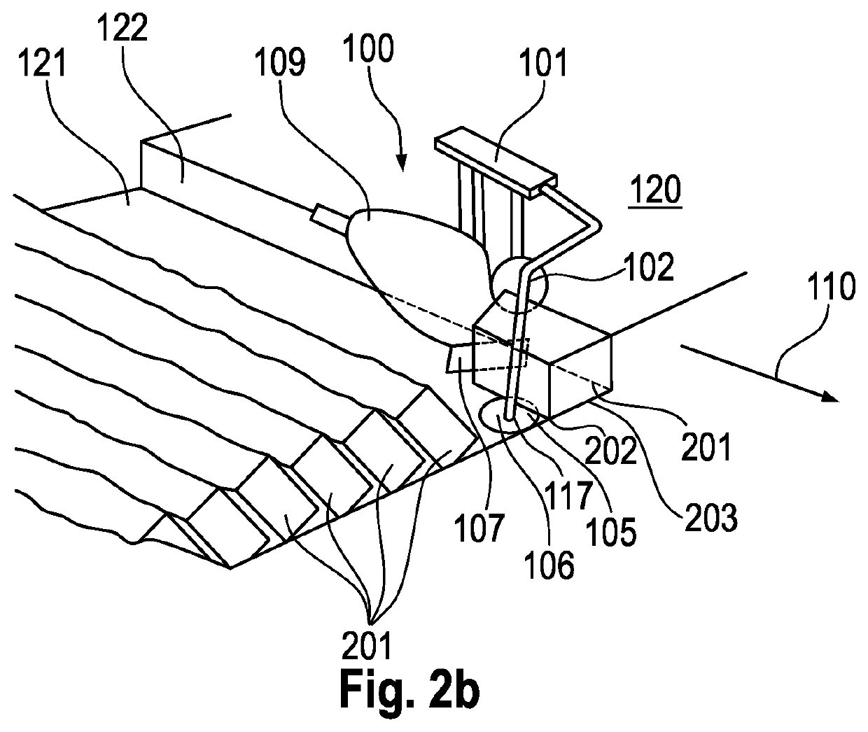
[0117]FIG. 1 shows a plow device 100 for plowing ground 120. A rotatable first cutting element 102 comprising a circumferential first cutting edge 103 is arranged on a support structure 101 and is designed such that a side region 202 of an earth ridge 201 of the ground 120 can be cut by means of a first cutting region 104 of the first cutting edge 103 when the support structure 101 is moved on the ground 120 in a plowing direction 110. A second cutting element 105 comprising a second cutting edge 106 is arranged on the support structure 101 and is designed such that a base region 203 of an earth ridge 201 of the ground 120 can be cut by means of a second cutting region 118 of the second cutting edge 106 when the support structure 101 is moved on the ground 120 in a plowing direction 110, the second cutting element 105 being arranged relative...


PUM


Abstract

A method for ploughing a ground (120) using a plough device (100). A rotatable first plate-like cutting element (102) having a circumferential first cutting edge (103) is arranged on a support structure (101) and is designed such that when the support structure (101) is moved on the ground (120) along a ploughing direction (110), a side region (202) of a soil ridge (201) of the ground (120) is being cut by means of a first cutting region (104) of the first cutting edge (103). A second preferably disc-shaped cutting element (105) having a second cutting edge (106) is arranged on the support structure (101) and is designed such that when the support structure (101) is moved on the ground (120) along a ploughing direction (110), a base region (203) of a soil ridge (201) of the ground (120) is being cut by means of a second cutting region (118) of the second cutting edge (106), wherein the second cutting element (105) is arranged relative to the first cutting element (102) in the ploughing direction (110) such that the second cutting region (118) is arranged before the first cutting region (104) in the ploughing direction (110).

Description

CROSS-REFERENCE TO RELATED APPLICATIONS[0001]This is a divisional application of U.S. patent application Ser. No. 16 / 483,798, filed Nov. 18, 2019, which is the United States national phase of International Patent Application No. PCT / EP2018 / 053313, filed Feb. 9, 2018, which claims priority to German Patent Application No. DE 10 2017 102 683.5, filed Feb. 10, 2017, the entire contents of each of which are hereby expressly incorporated by reference herein.TECHNICAL FIELD[0002]The present invention relates to a method for plowing ground using a plow device for plowing ground.BACKGROUND OF THE INVENTION[0003]Plows are considered to be one of the most important ground tillage devices in agriculture, and are available in a wide range of variants. Plows comprise, for example, a plowshare which cuts what is referred to as an earth ridge from the field to be plowed or from the meadow, as well as a moldboard which is a usually curved, helical metal element that adjoins the plowshare and that t...

Claims


Application Information

Patent Timeline
Patent Type & Authority Applications(United States)
IPC IPC(8): A01B13/12A01B9/00A01B15/08A01B15/16A01B17/00A01B49/02
CPCA01B13/12A01B9/003A01B15/08A01B15/16A01B17/00A01B49/025A01B9/00A01B13/08A01B5/00A01B15/18A01B35/18A01B49/02A01B79/00
Inventor HUBER, FRANZ-FERDINAND
Owner HUBER SOIL SOLUTION GMBH
Why Eureka
Try Eureka