Molar Implant and Method

Inactive Publication Date: 2008-11-13
SOUTHERN IMPLATS (PTY) LTD
View PDF13 Cites 23 Cited by
  • Summary
  • Abstract
  • Description
  • Claims
  • Application Information

AI Technical Summary

Benefits of technology

[0011]In preferred embodiments, there may be at least one external, longitudinally extending groove or flute intersectin

Problems solved by technology

However a problem with this conventional practice is that the root sockets are not centrally disposed with respect to the tooth itself.
This means that the implant is not centralised after c

Method used


Image

  • Molar Implant and Method
  • Molar Implant and Method
  • Molar Implant and Method

Examples


Embodiment Construction

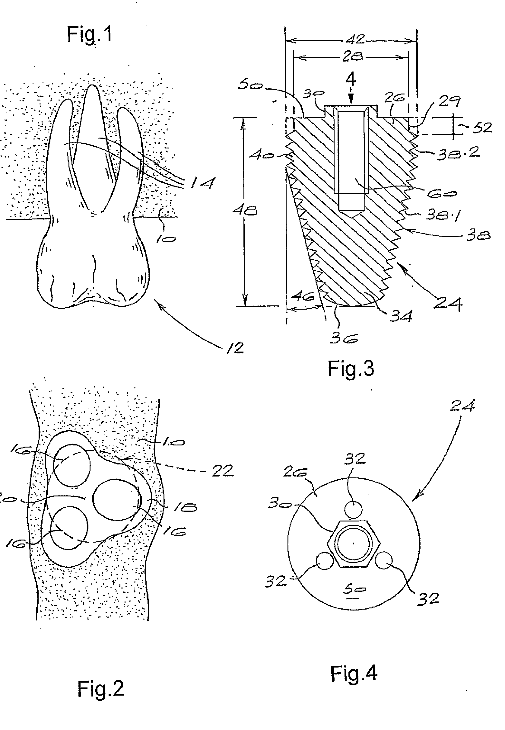
[0023]In FIGS. 1 and 2 a maxillary bone is indicated by the numeral 10. In FIG. 1, the numeral 12 indicates a molar tooth having three roots 14. Extraction of the tooth from the bone 10 leaves three corresponding root sockets 16, as shown in FIG. 2, with surrounding bone structure 18 having a central region 20 between the respective sockets.

[0024]As indicated previously conventional practice might be to anchor a molar implant in a selected one of the sockets 16. This can result in non-central placement of the implant, leading possibly to biomechanical and physiological problems in the final implant assembly. Also, in order to achieve primary stability in the anchorage of the implant to the bone, it is required that the implant have a threaded shank which is relatively slender to enable it to be screwed into the selected socket.

[0025]The present invention proposes a different implantation technique in which a hole indicated by the line 22 is drilled, reamed or otherwise formed centra...


PUM


Abstract

One aspect of the invention concerns a molar implant (24). The implant has a body with a coronal end (26) into which a threaded bore (60) extends to receive a fastener for a prosthesis. There is an externally threaded shank (34) extending apically from the outer end, at least a portion of the shank being inwardly tapered. The coronal end has a diameter of at least 7 mm and the shank has a taper angle in the range 10° to 25°. Another aspect of the invention concerns a surgical method in which a molar tooth (12) is extracted from a maxilla or mandible and a hole (22) is formed in the bone (10) of the maxilla or mandible at a generally central position relative to the sockets (16) left by the extracted molar tooth. This hole typically has a diameter greater than the lateral dimensions of the sockets. It is then possible to screw into the hole an implant (24) as described above.

Description

CROSS-REFERENCE TO RELATED APPLICATION[0001]This application is a National Phase of International Application Serial No. PCT / IB06 / 01373, filed 26 May 2006.BACKGROUND TO THE INVENTION[0002]THIS invention relates to a molar implant, i.e. a dental implant designed for use in molar implantation, and to a surgical method.[0003]Commonly used dental implant assemblies include an implant which is implanted in a patient's jawbone and a prosthesis, typically in the form of a prosthetic tooth or abutment, which is subsequently anchored to the implant. The implant typically has a tapered, threaded shank which is screwed into a hole in the jawbone.[0004]Molar teeth usually have multiple roots, often three in the case of maxillary molar teeth and two in the case of mandibular molar teeth. When a molar tooth is extracted the roots leave multiple root sockets with relatively small lateral dimensions in the jawbone. In common implantation practice, the shank of the implant is screwed into a selected...

Claims


Application Information

Patent Timeline
IPC IPC(8): A61C8/00
CPCA61C8/0022A61C8/0075
Inventor ACKERMANN, ANDREW
Owner SOUTHERN IMPLATS (PTY) LTD
Why Eureka
Try Eureka