Methods and systems for wheel balancer matching and flat spot correction

a technology of wheel balancer and flat spot correction, which is applied in vehicle tyre testing, instruments, roads, etc., can solve the problems of increasing flat spot problem, noticeable thumping or slapping sound, and more susceptible compositions to a condition, so as to reduce the spectral density analysis value

Inactive Publication Date: 2008-11-20
HUNTER ENG
View PDF9 Cites 13 Cited by
  • Summary
  • Abstract
  • Description
  • Claims
  • Application Information

AI Technical Summary

Benefits of technology

[0006]In another embodiment, a method of matching a tire to a rim of a wheel includes mounting a wheel assembly on the balancer spindle, determining radial force variation of the wheel assembly, and analyzing the tire force variation using spectral density analysis. The method also optionally includes outputting a relative rotational mounting position of the tire with respect to the wheel rim to minimize the spectral density analysis value.

Problems solved by technology

Some of such compositions may be more susceptible to a condition commonly referred to as “flatspotting.” Recent evidence suggests that the flat spotting problem has been escalating because of the increased use of low profile, increased sidewall stiffness tires.
As the tire rotates, there is a noticeable thumping or slapping sound resulting from the flat spot on the tire.
Although severe radial force variation issues can be caused by flat spotted tires, no known wheel balancers are able to recognize a flat spot.
Known techniques require the flat spot to be massaged out of the tire before balancing and / or computing the matching mark locations for the rim and tire, therefore errors and an improper diagnosis occur for this possibly temporary condition.
Not only is this an unreasonable task for shops to perform but they have no way of knowing if any of the tires are even flat spotted to begin with.

Method used


Image

  • Methods and systems for wheel balancer matching and flat spot correction
  • Methods and systems for wheel balancer matching and flat spot correction
  • Methods and systems for wheel balancer matching and flat spot correction

Examples


Embodiment Construction

[0016]The following detailed description illustrates the invention by way of example and not by way of limitation. The description clearly enables one skilled in the art to make and use the invention, describes several embodiments, adaptations, variations, alternatives, and uses of the invention, including what is presently believed to be the best mode of carrying out the invention.

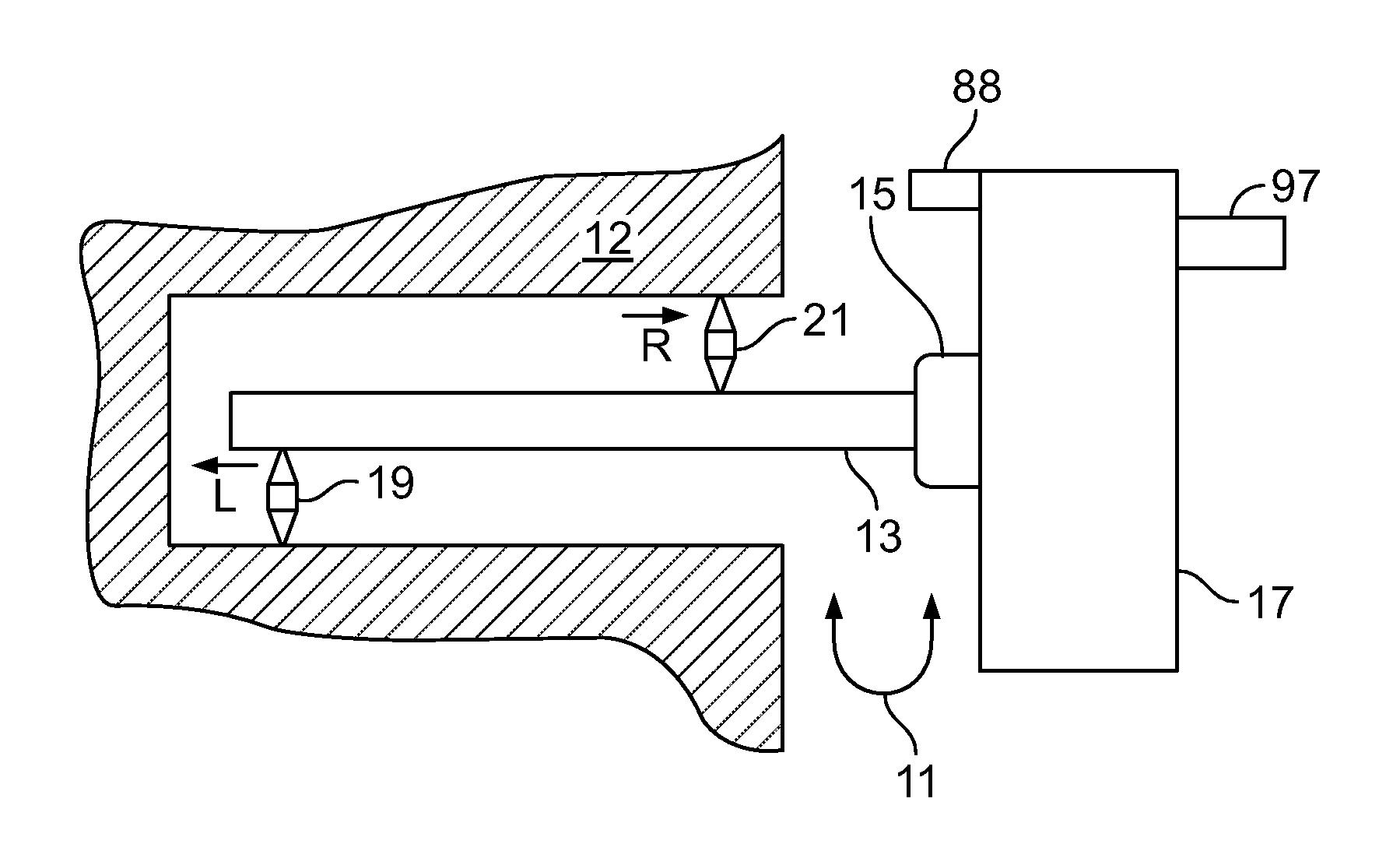
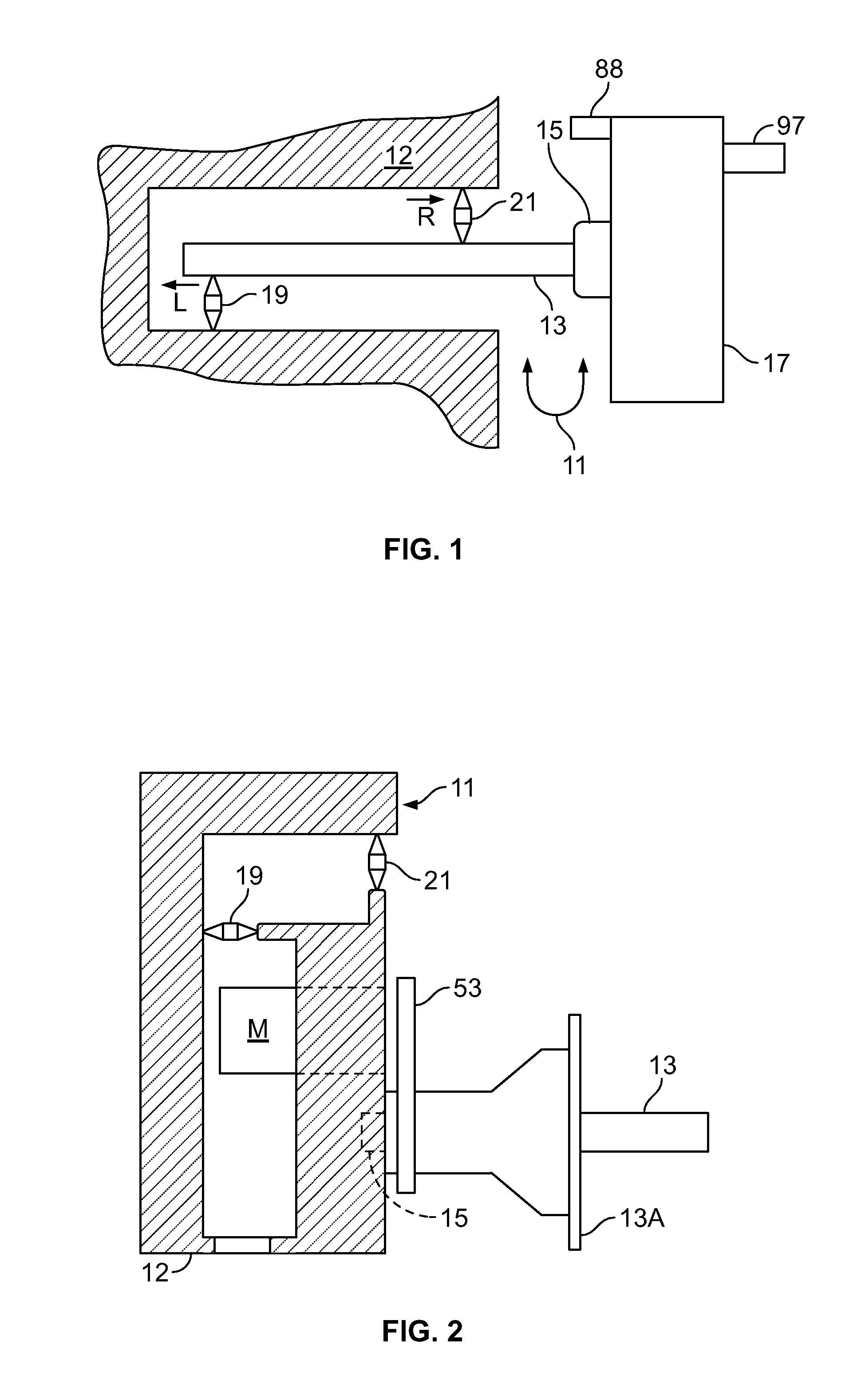
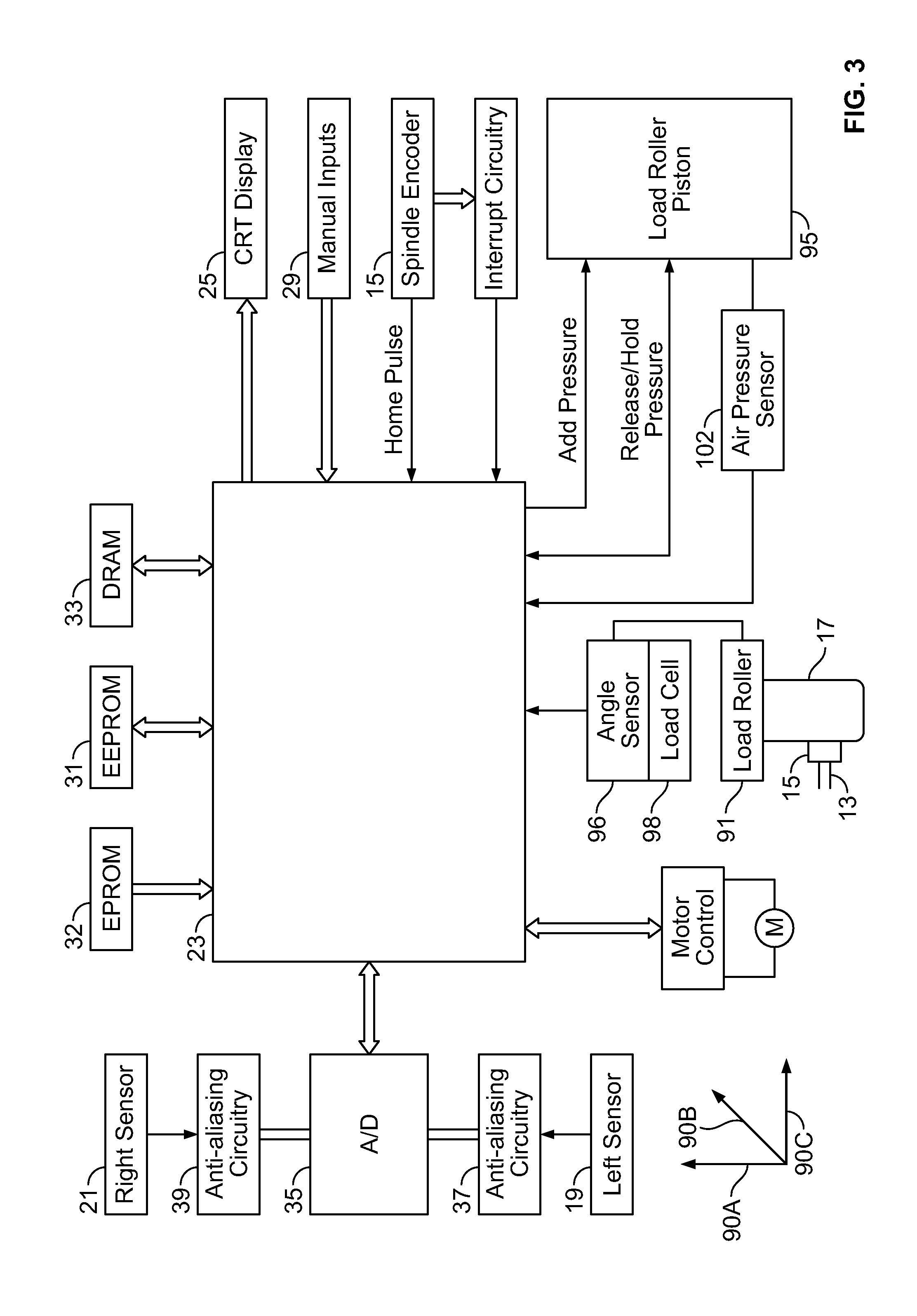
[0017]FIG. 1 is a schematic diagram of a wheel balancer 11 in accordance with an embodiment of the present invention. The particular balancer shown is illustrative only, since the particular devices and structures used to obtain imbalance, runout, and force variation information could readily be changed without changing the present invention. Balancer 11 includes a rotatable shaft or spindle 13 driven by a suitable drive mechanism such as a motor M and drive belt 53 (shown in FIG. 2). A shaft encoder 15 coupled to shaft 13 is configured to provide speed and rotational position information to control circu...


PUM


Abstract

Methods and systems for a computer implemented method of analyzing a vehicle wheel assembly including a tire and a rim is provided. The method includes removably mounting a wheel assembly on a shaft having a longitudinal axis and being rotatable about the longitudinal axis to rotate the wheel assembly, applying a substantially radial force to the wheel assembly during rotation thereof, and measuring variations in the radial force from at least one of radial runout, tire uniformity, and tire flatspotting. The method also includes determining a condition of the wheel assembly based on a spectral density analysis of the measured variations.

Description

CROSS REFERENCE TO RELATED APPLICATIONS[0001]This application claims priority to and the benefit of the filing date of U.S. Provisional Application No. 60 / 938,656 filed on May 17, 2007, which is hereby incorporated by reference in its entirety.BACKGROUND OF THE INVENTION[0002]This invention relates generally to balancing vehicle wheels and more particularly, to methods and systems for matching vehicle wheels using a balancer that includes a load roller.[0003]At least some known vehicle wheel assemblies use tires comprising a number of different material compositions. Some of such compositions may be more susceptible to a condition commonly referred to as “flatspotting.” Recent evidence suggests that the flat spotting problem has been escalating because of the increased use of low profile, increased sidewall stiffness tires. Most often the flat spotting is caused by the vehicle sitting in a parking lot, especially in hot weather. Extreme cases occur with long term vehicle storage by ...

Claims


Application Information

Patent Timeline
Patent Type & Authority Applications(United States)
IPC IPC(8): G01M1/16
CPCG01M1/16
Inventor DOUGLAS, MICHAEL WAYNESCRIBNER, DAVID MERRILLCLASQUIN, JOEL ALLEN
Owner HUNTER ENG
Why Eureka
Try Eureka