Clutch Structure for Presser Foot of Embroidery Sewing Machine

a technology of embroidery sewing machine and clamping structure, which is applied in the direction of embroidering machine, feeder, textiles and paper, etc., can solve the problems of vibration and noise inside the sewing arm, and achieve the effect of preventing unnecessary driving of the presser foot and relieving vibration and nois

Inactive Publication Date: 2008-11-20
SUSR PRECISION CO LTD
View PDF6 Cites 19 Cited by
  • Summary
  • Abstract
  • Description
  • Claims
  • Application Information

AI Technical Summary

Benefits of technology

[0016]The present invention has been made to solve the foregoing problems with the prior art, and therefore the present invention provides a clutch...

Problems solved by technology

Further, there is a problem in that upon such an operation, as the presser foot 128 is driven in the no...

Method used


Image

  • Clutch Structure for Presser Foot of Embroidery Sewing Machine
  • Clutch Structure for Presser Foot of Embroidery Sewing Machine
  • Clutch Structure for Presser Foot of Embroidery Sewing Machine

Examples


Embodiment Construction

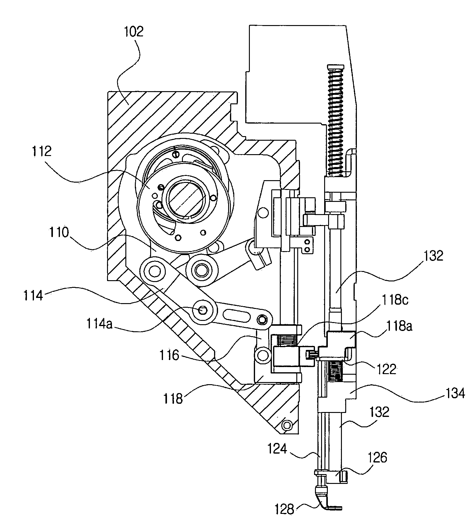
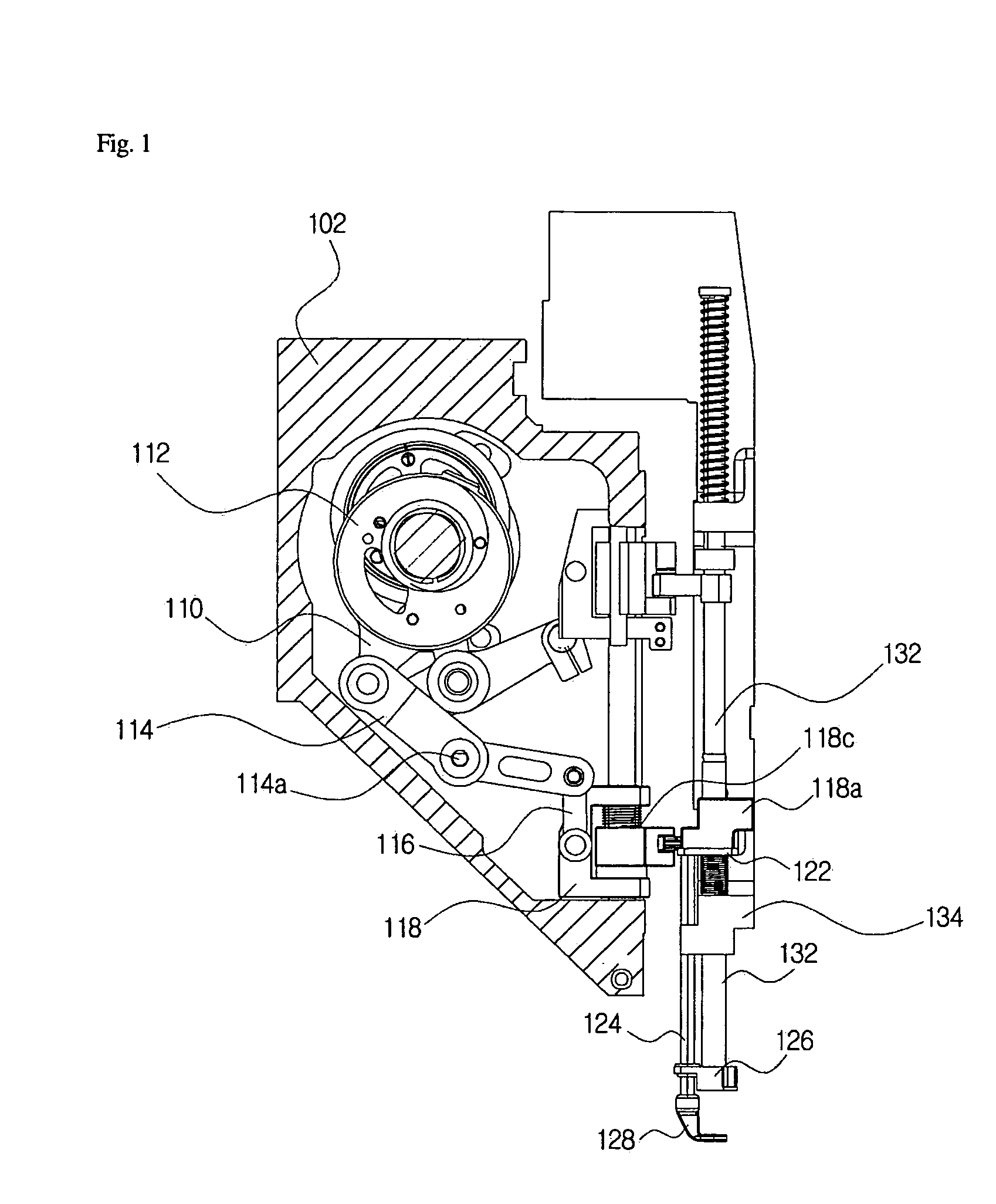
[0032]Hereinafter, a clutch structure for a presser foot in an embroidery sewing machine according to the present invention will be described more fully with reference to the accompanying drawings, wherein like reference numerals refer to like elements.

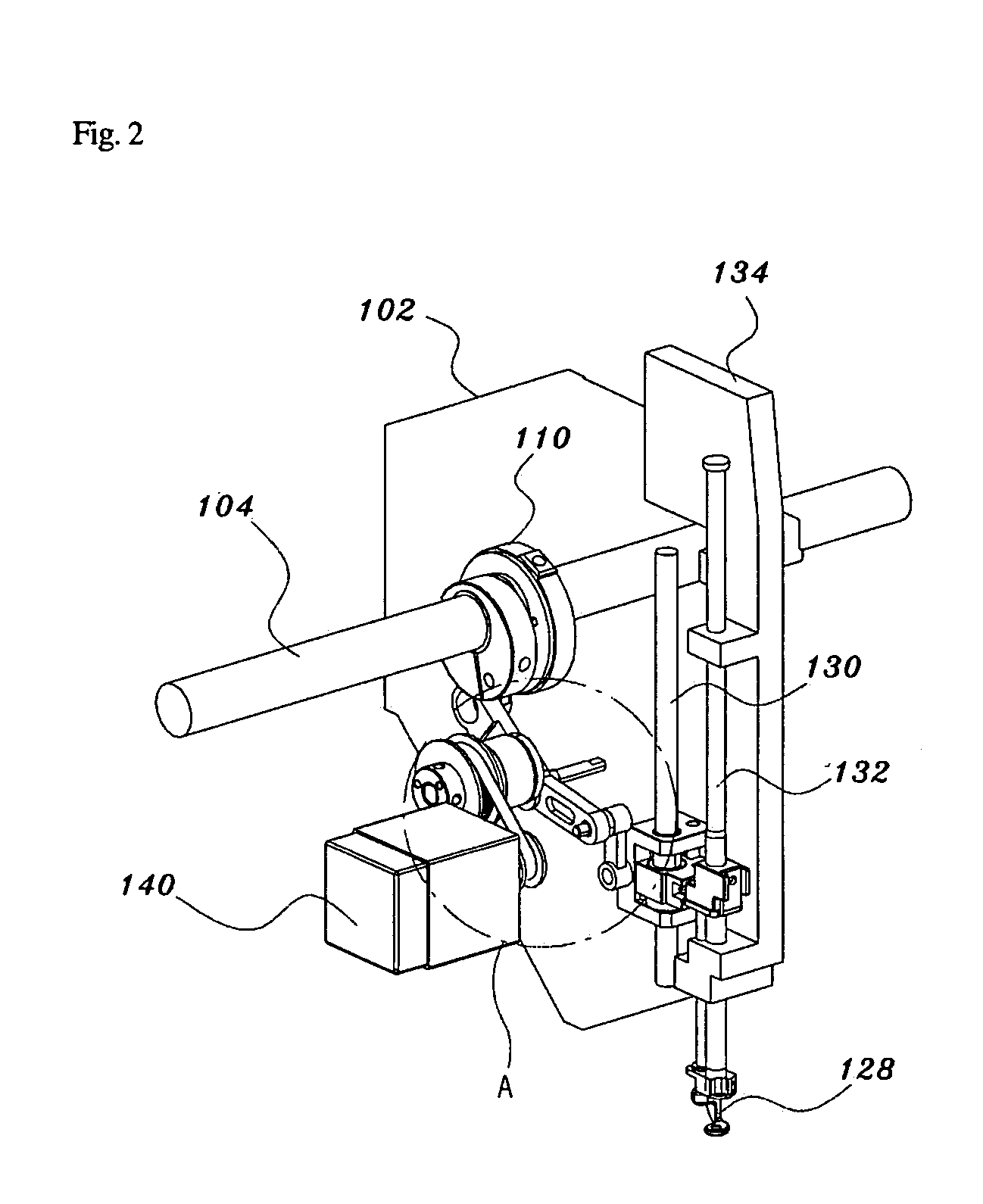
[0033]FIG. 4 is a perspective view and a partially enlarged exploded perspective view illustrating a clutch structure for a presser foot in an embroidery sewing machine according to the present invention, in the mounted position, FIG. 5A is a perspective view illustrating the assembled clutch structure for the presser foot of the embroidery sewing machine according to the present invention, seen from one direction, and FIG. 5B is a perspective view illustrating the assembled clutch structure for the presser foot of the embroidery sewing machine according to the present invention, seen from the other direction.

[0034]Referring to these drawings, the clutch structure for the presser foot of the embroidery sewing machine according to the ...


PUM


Abstract

A clutch structure for a presser foot in an embroidery sewing machine is provided. The clutch structure includes a guide member, to which the presser foot drive link is rotatably connected, and through which the needle bar guide shaft passes, a spring connecting member mounted on the outer circumference of the needle bar guide shaft and inside the guide member, a resilient member mounted on the outer periphery of the spring connecting member, and a pivot member mounted inside the guide member so as to be pivotable around the needle bar guide shaft within a certain angular range by the height adjusting mechanism and the resilient member. Upon a head-interval adjusting operation, the unnecessary driving of the presser foot is prevented, so that the occurrence of vibrations and noise as well as the unnecessary wear of a needle bar, a presser foot support, and a presser foot holder can be prevented.

Description

BACKGROUND OF THE INVENTION[0001]1. Field of the Invention[0002]The present invention relates to an embroidery sewing machine, and more particularly, to a clutch structure for a presser foot in an embroidery sewing machine, which upon a head-interval adjusting operation, can prevent unnecessary driving of a presser foot (a cloth pressing member), thereby preemptively avoiding the occurrence of vibration and noise caused by the unnecessary driving of the presser foot, as well as unnecessary wear of a needle bar installed in a needle bar support case so as to be able to move up and down, a presser foot support, and a presser foot holder.[0003]2. Description of the Related Art[0004]Generally, an embroidery sewing machine is a biaxial positioning control machine, in which an embroidery stitch frame for fixing fabric undergoes horizontal motion in x-axis and y-axis directions while a needle bar moves up and down.[0005]Since such an embroidery sewing machine does needlework while the embr...

Claims


Application Information

Patent Timeline
IPC IPC(8): D05B29/00
CPCD05B69/32D05B29/02D05C9/20D05B29/04
Inventor JOE, SUN HWAN
Owner SUSR PRECISION CO LTD
Why Eureka
Try Eureka