Handheld medical image scanning auxiliary equipment

A technology for image scanning and auxiliary equipment, applied in the fields of application, medical science, acoustic wave diagnosis, etc., can solve problems such as laborious operation, and achieve the effect of improving scanning quality, reducing vibration and improving stability

Pending Publication Date: 2021-11-16
杨杰
View PDF1 Cites 0 Cited by
  • Summary
  • Abstract
  • Description
  • Claims
  • Application Information

AI Technical Summary

Problems solved by technology

The hand-held scanning auxiliary device in the above-mentioned patent has the following disadvantages: when performing peripheral scanning centering on a certain part, it is necessary to constantly adjust the picking position of the mobile device, and it is laborious to operate for a long time

Method used


Image

  • Handheld medical image scanning auxiliary equipment
  • Handheld medical image scanning auxiliary equipment
  • Handheld medical image scanning auxiliary equipment

Examples


Embodiment 1

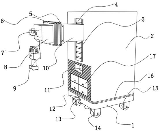
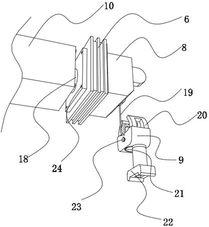
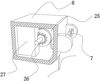
[0033] A handheld medical image scanning auxiliary device, such as figure 1 , figure 2 and Figure 4 , Figure 5As shown, it includes a body 2, the outer wall of one side of the body 2 is connected with a moving seat 10 through a displacement adjustment part, and the inner wall of one side of the moving seat 10 is fixed with a telescopic piece 18 by a bolt, and the telescopic piece 18 is a hydraulic cylinder, an air cylinder Or electric telescopic columns, etc., the extension end of the telescopic member 18 is fixed with a connecting seat 8 by bolts, one side of the connecting seat 8 is connected with a handle 9 through an automatic winding part, and the outer walls of both sides of the handle 9 are plugged with Pressing head 23, one side outer wall of pressing head 23 is welded with push plate 32, and the outer wall of push plate 32 and one side inner wall of handle 9 are welded with same first elastic member 33, facilitates pressing head 23 by arranging first elastic memb...

Embodiment 2

[0039] A handheld medical image scanning auxiliary device, such as figure 1 As shown, in order to facilitate changing the place of use; this embodiment makes the following improvements on the basis of embodiment 1: a locker 17 is plugged into one side of the outer wall of the body 2; a shock absorber is welded to the outer wall of the bottom of the body 2 Pad 16, the bottom outer wall of shock-absorbing pad 16 is connected with base 1 in rotation; The inner wall is slidably connected with a footboard 13, and one side outer wall of the footboard 13 is fixed with a suction cup 14 which forms a sliding fit with the bottom outer wall of the base 1 by bolts. By setting the locker 17, it is convenient for the medical staff to place the articles for use; push the body 2 to change the place of use by moving the legs 15, and set the shock absorbing pad 16 to relieve the vibration during the movement of the equipment. After arriving at the destination, step on the presser foot Pedal 13...


PUM


Abstract

The invention discloses handheld medical image scanning auxiliary equipment, and relates to the technical field of medical image auxiliary equipment. The problem that it is strenuous to control the position of equipment is solved. The equipment specifically comprises a device body, the outer wall of one side of the device body is connected with a moving seat through a displacement adjusting part, the inner wall of one side of the moving seat is fixedly connected with a telescopic piece, the extending end of the telescopic piece is fixedly connected with a connecting seat, one side face of the connecting seat is connected with a handle through an automatic winding part, and pressing heads are arranged on the outer walls of the two sides of the handle. The outer wall of one side of the pressing head is fixedly connected with a push plate, and the outer wall of the push plate and the inner wall of one side of the handle are fixedly connected with the same first elastic piece. Lifting grooves are formed in the inner walls of the opposite sides of the handle correspondingly, and the inner walls of the lifting grooves are slidably connected with pressing plates through sliding blocks. According to the invention, the turnover position and the moving speed of the scanner with the detection part as the center can be flexibly and automatically adjusted according to detection requirements.

Description

technical field [0001] The invention relates to the technical field of medical imaging auxiliary equipment, in particular to a hand-held medical image scanning auxiliary equipment. Background technique [0002] Medical ultrasound imaging technology is today's mainstream method for easy and non-invasive assessment of the detailed internal structure of tissues and organs for assessment, diagnosis, prescribed treatment options, and determination of efficacy. Conventional ultrasound images of medical imaging equipment in the prior art are two-dimensional, and the diagnostician must convert multiple two-dimensional images in his mind to form a complex three-dimensional structure, which will cause variability and sometimes lead to inaccuracies. correct diagnosis. [0003] In order to solve the above problems, after searching, the Chinese patent application number is CN201420564590.6, which discloses a hand-held scanning auxiliary device, including an "H" shaped hollow shell, and ...

Claims


Application Information

Patent Timeline
Patent Type & Authority Applications(China)
IPC IPC(8): A61B8/00B65H75/38B65H75/48
CPCA61B8/4427B65H75/48B65H75/38
Inventor 杨杰刘芸
Owner 杨杰
Why Eureka
Try Eureka