
Handheld adhesive applicator

Inactive Publication Date: 2008-11-20
RS IND
View PDF32 Cites 2 Cited by
  • Summary
  • Abstract
  • Description
  • Claims
  • Application Information

AI Technical Summary

Benefits of technology

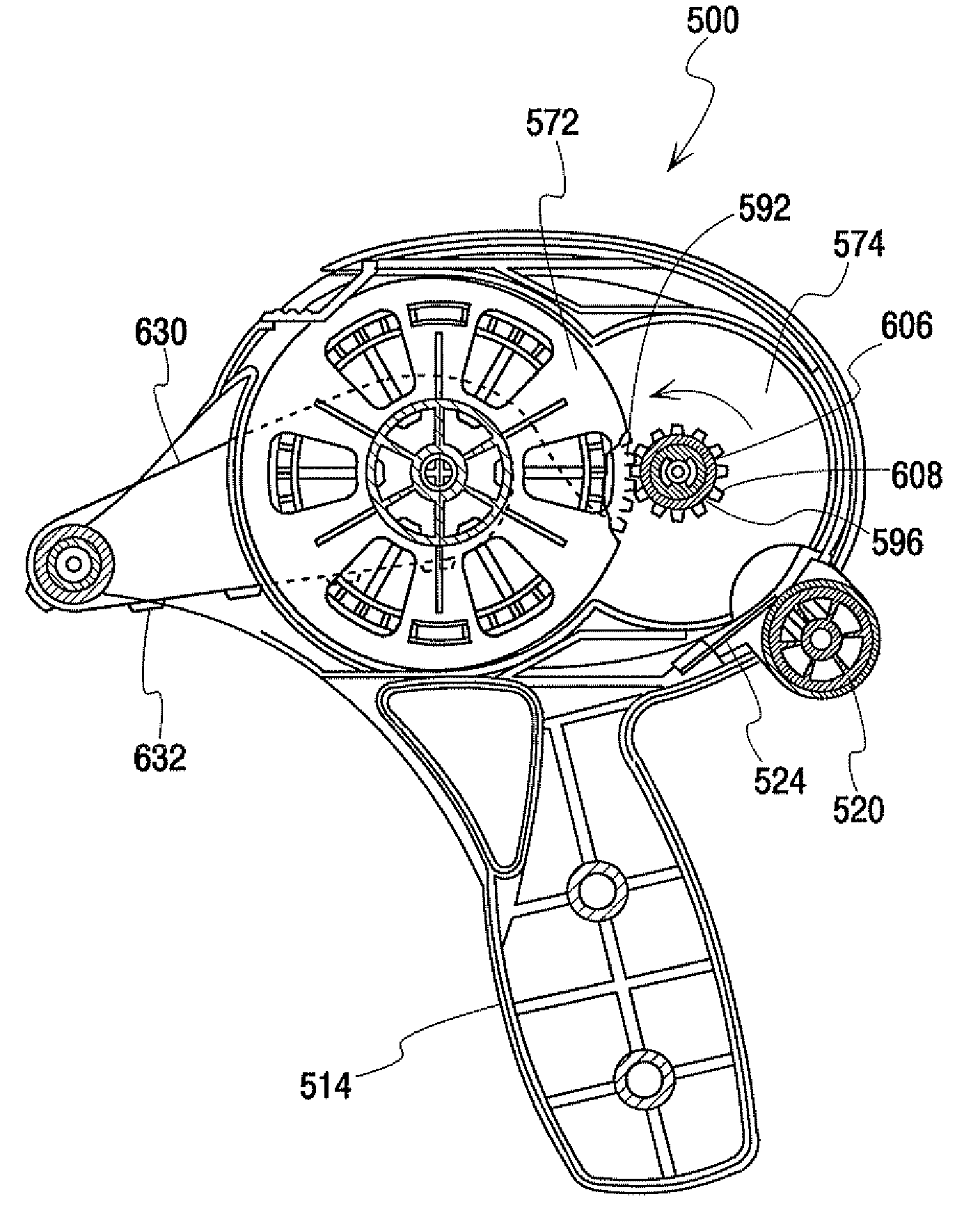
[0008]In accordance with one embodiment or aspect of the present disclosure, a handheld adhesive applicator is provided with a housing assembly, a cartridge assembly removably connected to the housing assembly, and a handle assembly removably connected to the housing assembly. The cartridge assembly includes a primary spool for mounting an adhesive segment roll and a secondary spool for automatically winding a spent portion of adhesive segment roll. A gear arrangement allows for numerous adhesive segments to be applied consecutively in a glide-type application or for a single adhesive segment to be accurately applied using a manual advance feature. The removable handle may be gripped during a primary mode of operation or removed for a secondary mode of operation in which the housing assembly is gripped during use.

Problems solved by technology

However, there are numerous practical problems with such a method.
For example, pressure-sensitive adhesive segments by their nature are, of course, sticky and gummy.
Because of the stickiness of the adhesive segment, it is often difficult to transfer the adhesive segment from the hand to an object.
Not applying the adhesive segment in its original shape nor in an even layer affects the adhesive segment's strength of adhesion.
Furthermore, the human hand has oils that can negatively affect the adhesion and can also bring acid to the surface, adversely affecting long term archivability.
There are a number of disadvantages associated with known handheld adhesive applicators, most notably their general lack of operational flexibility.
But these devices are poorly suited for other types of applications, such as those requiring the repeated application of a single adhesive segment.
Other known handheld devices are provided with a pistol-grip handle that is suitable for some applications, but obtrusive for other applications.
Additional disadvantages include the small roll capacity of some known devices and the need to manually thread and secure a new roll after a first adhesive segment roll has been exhausted.

Method used


Image

  • Handheld adhesive applicator
  • Handheld adhesive applicator
  • Handheld adhesive applicator

Examples


Embodiment Construction

[0086]Detailed embodiments of the present invention are disclosed herein. However, it is to be understood that the disclosed embodiments are merely exemplary of the invention, which may be embodied in various forms. Therefore, specific details disclosed herein are not to be interpreted as limiting, but merely as a basis for the claims and as a representative basis for teaching one skilled in the art to variously employ the present invention in virtually any appropriate manner.

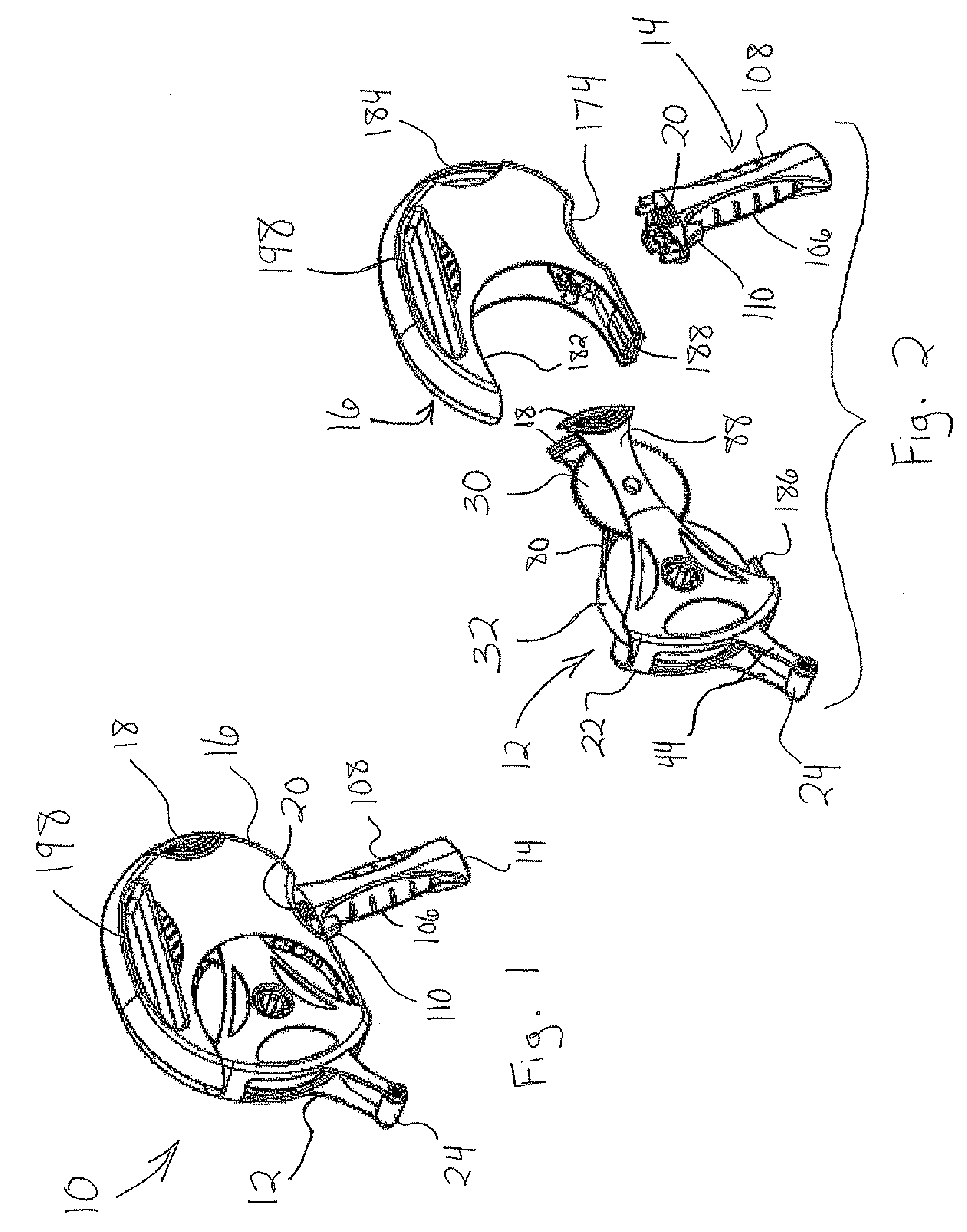
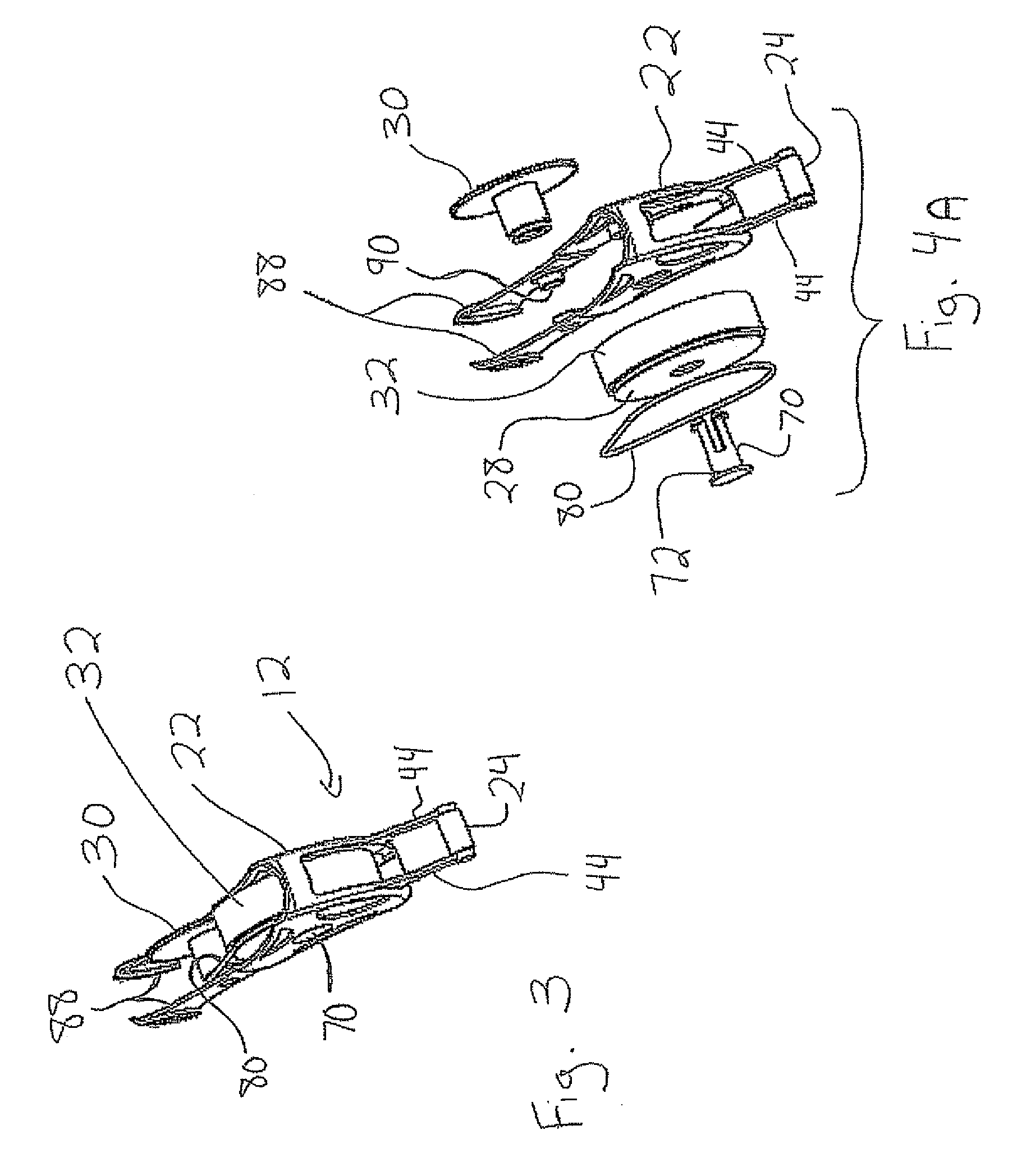
[0087]FIG. 1 illustrates one embodiment of a handheld adhesive applicator 10 of the present disclosure. FIG. 2 is an exploded view of the handheld adhesive applicator 10, which shows three main subassemblies—a cartridge assembly 12, a handle assembly 14, and a housing assembly 16. The subassemblies can be primarily comprised of a lightweight plastic material. The cartridge assembly 12 is provided with clips 18 that allow the cartridge assembly to releasably lock into the housing assembly 16 without the need for...


PUM

PropertyMeasurementUnit
Forceaaaaaaaaaa
Speedaaaaaaaaaa

Abstract

A handheld adhesive applicator is provided with a housing assembly, a cartridge assembly removably connected to the housing assembly, and a handle assembly removably connected to the housing assembly. The cartridge assembly includes a primary spool for mounting an adhesive segment roll and a secondary spool for automatically winding a spent portion of the adhesive segment roll. A gear arrangement allows for numerous adhesive segments to be applied consecutively in a glide-type application or for a single adhesive segment to be accurately applied using a manual advance feature. The removable handle may be gripped during a primary mode of operation or removed for a secondary mode of operation in which the housing assembly is gripped during use.

Description

[0001]The present application claims the benefit of U.S. Provisional Application Nos. 60 / 917,987 and 60 / 917,986, both filed May 15, 2007 and U.S. Provisional Application Nos. 60 / 987,506 and 60 / 987,491, both filed Nov. 13, 2007, all of which are incorporated by reference.FIELD OF THE INVENTION[0002]This disclosure generally relates to the application of pressure-sensitive adhesive segments from a release liner. More particularly, this disclosure relates to handheld devices for applying pressure-sensitive adhesive segments from a release liner.DESCRIPTION OF RELATED ART[0003]Hobbyists and home craft artists, particularly those involved in scrapbooking, commonly use pressure-sensitive adhesive segments dispensed from a release liner to attach displayed objects, such as photographs, newspaper clippings and other such memorabilia, to a substrate such as scrapbook pages or other display medium. The pressure-sensitive adhesive segments are typically arranged seriatim on the release liner i...

Claims


Application Information

Patent Timeline
IPC IPC(8): B29C65/52B65D85/00
CPCB29C65/08B29C66/54B29L2031/283B65H37/005B65H2701/19402Y10T156/17Y10T156/1365Y10T156/1788Y10T156/1348Y10T156/18Y10T156/1795Y10T225/246
Inventor ALLEN, SCOTT M.TRETTIN, DAVID J.
Owner RS IND
Learn More