
Machine learning network based carriage control apparatus for maintenence striping

Pending Publication Date: 2021-10-21
LIMNTECH
View PDF0 Cites 0 Cited by
  • Summary
  • Abstract
  • Description
  • Claims
  • Application Information

AI Technical Summary

Benefits of technology

The invention provides a better way to put new markings on roads without needing an operator. It uses machine learning and visual technology to detect and locate the old markings accurately. This makes it easier to apply the new markings and reduces the risk of mistakes.

Problems solved by technology

All the above roadway mark materials are effective for visibly defining the roadway lane demarcation marks during daytime and clear weather conditions but are less effective during wet and nighttime conditions.
Because the larger diameter beads protrude significantly above the road surface, however, they are more susceptible to degradation over time.
This initially high contrast differentiation tends to degrade over time, however, for various reasons.
For example, the actual binder material which defines the visible reflective shape of the roadway mark (usually rectangular shaped) may become worn with vehicular traffic and the passage of time, and may further become discolored because of lengthy exposure times to ultra-violet radiation from the sun.
Further, black tire scuff marks may occur on the surface of the roadway mark further degrading mark visibility.
Differences in the coefficients of thermal expansion between the binder material and roadway surface may also cause a physical separation between them further degrading the ability to maintain a consistently visible roadway mark.
Seasonal roadway temperature variations over time may cause cracking and peeling of the roadway mark further degrading the effectiveness of the marking.
The reflective elements for the liquid, thermoplastic, and tape applications which are installed along with their respective binder may wear away quickly as the result of frictional contact between the tires of passing traffic and the applied roadway mark.
Usually, the exact positions of the roadway lanes, and therefore the roadway marks defining those lanes, are not visible during the snow-plowing process thereby increasing the probability that the marks will be accidentally scraped and removed by the plow.
This particular reapplication process is costly and inefficient because it requires use of a dedicated and expensive piece of equipment (commonly referred to as a “grinding truck” or a “water blaster”) or a combination of marking-removal machines, to first remove the pre-existing worn lines, and then additional time and labor costs are required to again lay out a new roadway mark path and apply the new roadway marking.
Furthermore, the motoring public is inconvenienced as the result of traffic lane closure for both the removal and the subsequent layout and reapplication of the roadway marks.
This is not the case, however, for repetitive skip line patterns where the operators must continuously align the dispensing hardware over the pre-existing roadway mark and simultaneously monitor and adjust the paint truck dispensing system to ensure that the newly applied marking accurately reproduces the existing skip line pattern by periodically manually correcting the timing of when to begin, and when to end, the dispensing of the roadway mark material.
Variations in both truck speed, dispensing valve turn-on delay, and operator response time usually result in positional misalignment between the actual beginning, or leading edge, of the pre-existing roadway mark line segment and the starting edge of the newly applied mark line segment.
Trailing edge positional errors between the pre-existing mark and the newly applied mark may occur because of variations in truck speed, dispensing valve turn-off delays, and operator response time.
A slower moving truck increases the amount of time necessary, however, to re-apply the mark material over the pre-existing mark.
Although successful in dispensing new roadway mark material on top of a pre-existing roadway mark, the manual process is prone to human error based upon the fact that the operator must simultaneously laterally align the dispensing hardware and control the timing when to begin and end the dispensing of mark material.
In addition, the operator cannot accurately determine the actual length of the line segment and will usually dispense new roadway mark material over the entire length of the visible pre-existing line segment without regard to the original line segment specification.
With a manually controlling restriping process, the operator may overly dispense and restripe the entire 17-foot (520 cm) line segment even though the original specification calls for a 15-foot (450 cm) line segment, thus unnecessarily wasting a good percentage of roadway mark material.
For example, increases in tire temperature during the restriping process may cause a change in tire pressure.
This change in tire pressure may result in a change in tire diameter which may result in a distance error per tire revolution.
Other factors may also affect the distance travelled per tire revolution such as tire wear and tire deflation caused by leaking or inoperable tire valves.
Errors caused by changes in the distance-to-pulse ratio during the restriping process, or by using previous and not current ratios, are cumulative and cause positional errors in the painted line segment and gap lengths.
This dispensing cycle error is cumulative and continues throughout the restriping process, and if not quickly corrected results in an unacceptable restriped roadway mark pattern.
The positional accuracy of the partially automated restriping process is therefore dependent upon the accuracy and consistency of the calibration procedure and again on the judgment of the material-dispensing operators, and therefore is prone to errors.
Furthermore, the requirement that the operators have an unobstructed view of the roadway mark for both laterally aligning the carriage over the roadway mark and for advancing or delaying the timed dispensing cycle usually places the operators towards the rear of the paint vehicle and therefore in harm's way of high-speed passing or common lane traffic.
Documented operator injuries have occurred because of collisions between the rear portion of the paint truck and passing or common lane traffic.
Although this patent attempts to eliminate the operator from the rear of the paint truck, maintaining an accurate dispensing position over the pre-existing roadway mark is difficult because of the simultaneous tasks required of the driver to properly dispense the roadway mark material at exact times while maintaining both the truck and roadway material dispensing hardware alignment with the current roadway mark path, and also attempting to control the position of the paint truck along the pre-existing roadway mark path.
This situation rarely occurs because traffic has diminished the optical distinguishing characteristics of the previously applied mark or has completely removed the mark from the roadway surface.
These apparatus work well if the old-line marking is detectable by the marking detector but fail if some of the old-line marking has been completely obliterated along the current roadway mark path.
Reliable detection of the roadway mark requires, however, that the electromagnetic spectral emission response of the chemical constituents of the roadway mark material be matched with the wavelength of the illumination to achieve the greatest amount of stimulated (fluorescence) spectral emission, and if the mark is worn away by traffic it no longer provides stimulated emission.
None of the prior art addresses all these requirements.

Method used


Image

  • Machine learning network based carriage control apparatus for maintenence striping
  • Machine learning network based carriage control apparatus for maintenence striping
  • Machine learning network based carriage control apparatus for maintenence striping

Examples


second embodiment

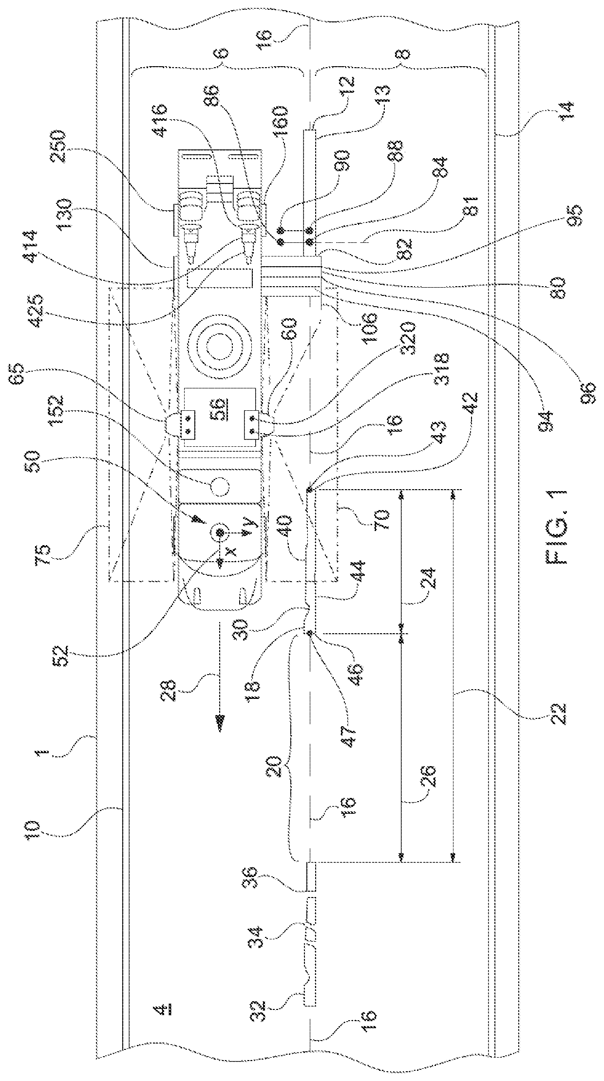
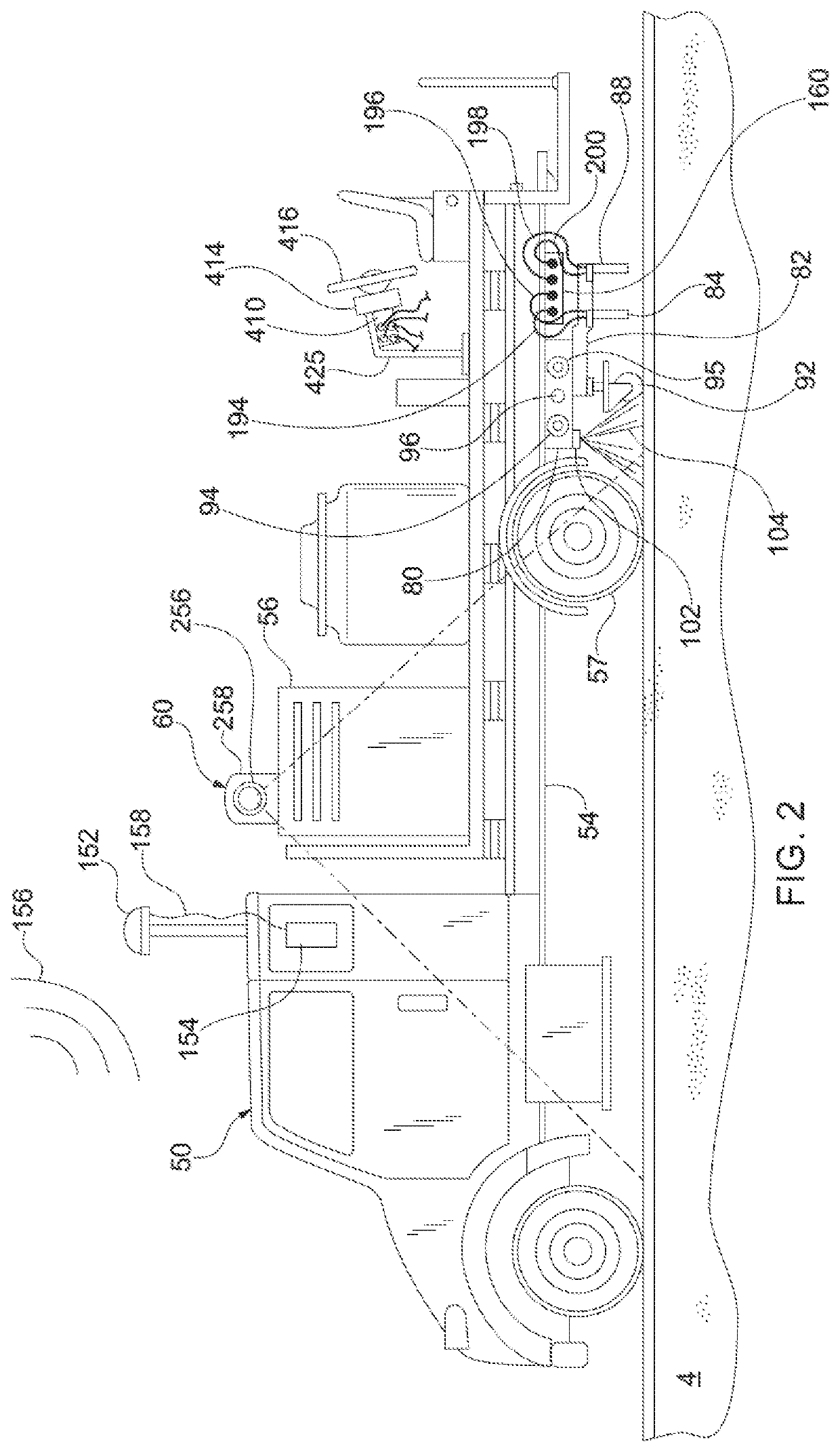
[0289]Referring to FIG. 15B, a block diagram of a machine-learning-network based carriage control system 1750 is shown which, in cooperation with programs 808, 810, 812, 814, 816, and 818, commands valve 427 to move carriage 80 via hydraulic system 401 in a lateral direction to align the paint gun 84 and the bead gun 88 over roadway mark segment 18.

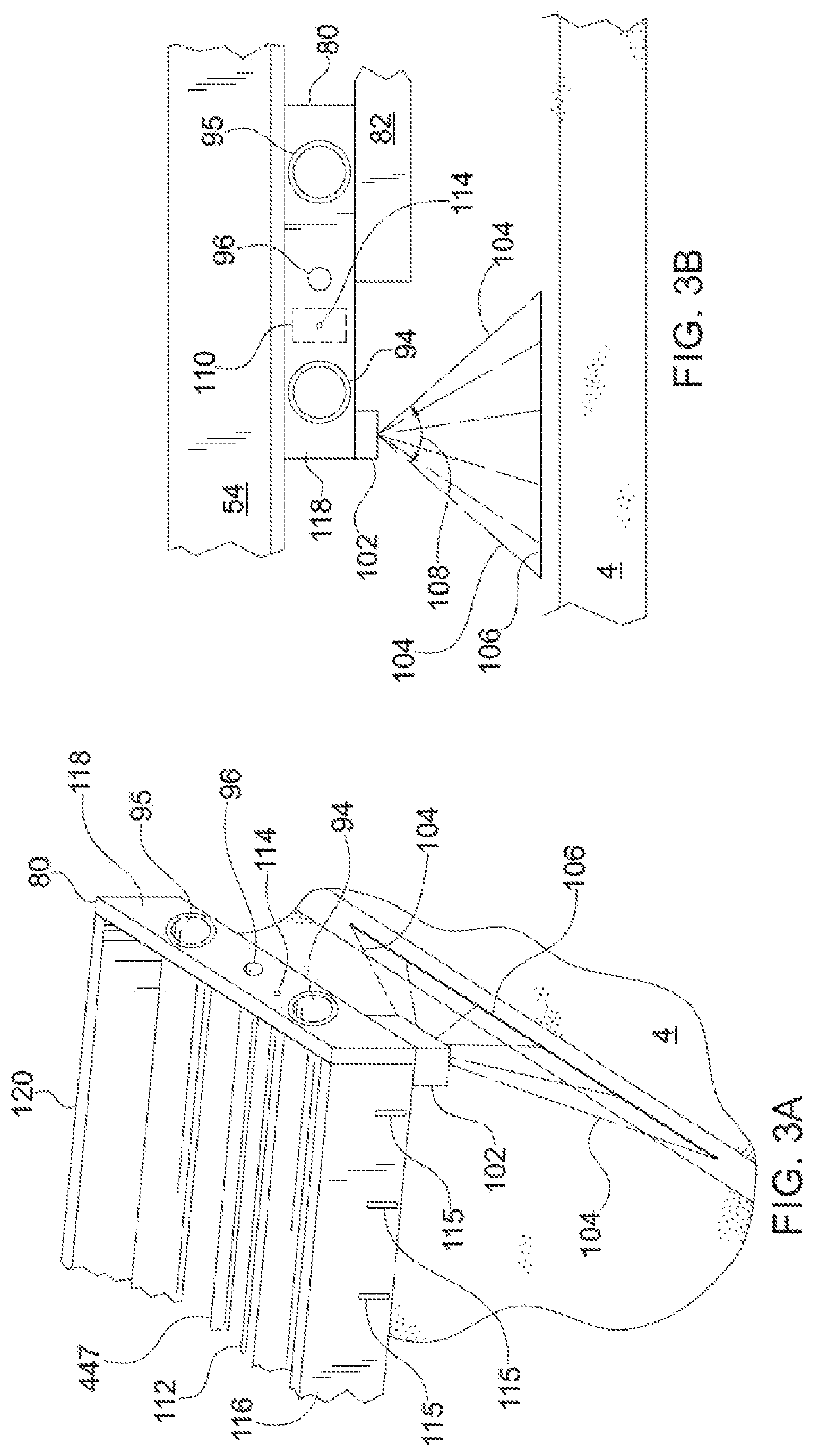
[0290]The machine-learning-network based carriage control system 1750 is similar to the control system 1700 except that the current lateral position of carriage 80 is determined from the coordinates of the image 106a of the laser line 106 (offset corrected). The coordinates of the imaged laser line 106a may be expressed in array or object space coordinates.

[0291]The imager 252 images both the roadway mark 18 and the laser line 106 combination and outputs this image to the image correction system 1725. The output from the image correction system 1725 then flows to the input of the image analyses system 1730.

[0292]The image analysis program...

first embodiment

[0307]In operation and referring additionally to FIGS. 17A and 17B, the process of maintenance striping of pre-existing skip line roadway marks using this invention begins with step 1100.

[0308]In step 1100, the operator positions vehicle 50 along a desired roadway mark path 16 having a roadway mark which needs to be restriped with location assistance being supplied by GPS receiver 154 and IMU 155 and LCD 704. It is assumed that all calibration and offset data have been previously obtained and are stored in data memory 806. The driver then inputs the desired line stripe pattern (single or double, solid or skip line(s), for example 15 / 40) and the type of roadway mark material (paint or paint and bead) to be dispensed using keyboard 706 and depresses the start button on keyboard 706. The desired line stripe pattern is entered into the image analysis system 1730.

[0309]Alternately, the driver may decide to enable the system 700 to determine the line stripe pattern by determining the leng...


PUM


Abstract

A control system for positioning a marker over a pre-existing roadway surface mark. The control system has one or more imagers having a field of view for imaging an area of roadway mark surface encompassing the roadway mark and a computer having a machine learning network to process the roadway mark image and position the marker over the pre-existing roadway mark.

Description

CROSS REFERENCE TO RELATED APPLICATION[0001]This application claims the benefit of U.S. Provisional Application No. 63 / 010,876, titled, “Machine Learning Based Carriage Control Apparatus For Maintenance Striping,” filed Apr. 16, 2020, the content of which is incorporated herein by reference in its entirety.TECHNICAL FIELD OF THE INVENTION[0002]This present invention relates generally to equipment for applying roadway lane demarcation markings onto a roadway surface and, in particular, to equipment for maintaining pre-existing roadway lane marks by automatically applying new roadway marking material from a moving vehicle directly over and on top of a pre-existing roadway mark using machine learning network and machine vision technologies.BACKGROUND OF THE INVENTION[0003]Existing roadway surfaces will typically include roadway lane demarcation markings to assist motorists for visually identifying lanes for controlling and directing traffic. In many cases the roadway markings are place...

Claims


Application Information

Patent Timeline
IPC IPC(8): G06K9/00G05D1/02G01S17/89G01S17/87G06N3/08G06V10/98
CPCG06K9/00798G05D1/0221G01S17/89G06K2209/21G06N3/08G05D2201/0213G01S17/87G05D1/0088G05D1/0246G01S17/88G06V20/588G06V10/98G06N20/10G06N3/045G06V2201/07G05D1/81
Inventor DOLINAR, DOUGLAS D.HALLER, WILLIAM R.DRAZBA, CHARLES R.SMITH, MATT W.LEONARD, KYLE J.STAHL, ERIC M.
Owner LIMNTECH
Learn More