
Anti-whiplash vehicle seat

a vehicle seat and anti-whiplash technology, applied in the field of vehicle seats, can solve the problem of severe loading on the rear wall of the seat componen

Inactive Publication Date: 2008-11-20
FAURECIA AUTOSITZE
View PDF15 Cites 3 Cited by
  • Summary
  • Abstract
  • Description
  • Claims
  • Application Information

AI Technical Summary

Problems solved by technology

In the event of an impact from the rear, the rear wall of the seat component is subjected to a severe loading by the occupant plunging a small distance into it.

Method used


Image

  • Anti-whiplash vehicle seat
  • Anti-whiplash vehicle seat
  • Anti-whiplash vehicle seat

Examples


Embodiment Construction

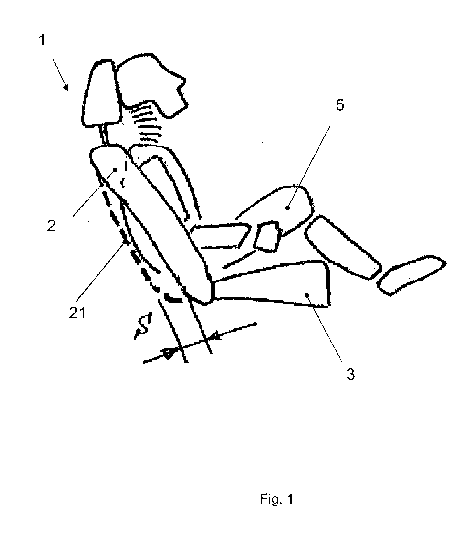
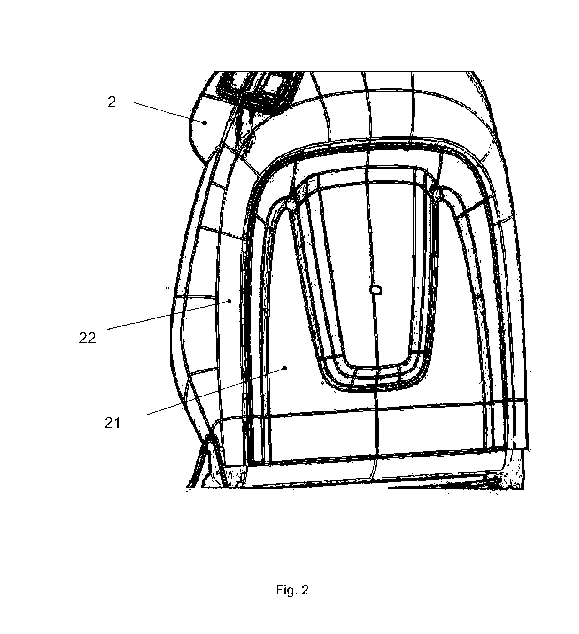
[0036]FIG. 1 shows a lateral schematic diagram of an exemplary embodiment of an anti-whiplash vehicle seat 1. FIG. 2 shows a detail of the anti-whiplash vehicle seat 1 in a rear view. The anti-whiplash vehicle seat 1 comprises a seat surface 3 and a backrest 2. The backrest 2 comprises a rear backrest covering with a fixed (but, if appropriate, soft or upholstered) side part 22 and a dimensionally stable central part 21. Within the meaning of the invention, the side part may be entirely or partially part of a lateral backrest lining. In the present case, the side part 22 is elastic. The anti whiplash vehicle seat 1 is configured—as can be seen in FIG. 1—in such a manner that it allows an occupant 5 or his body to plunge in by a distance S (of between 60 mm and 200 mm depending on the configuration) in the event of an appropriately severe impact from the rear.

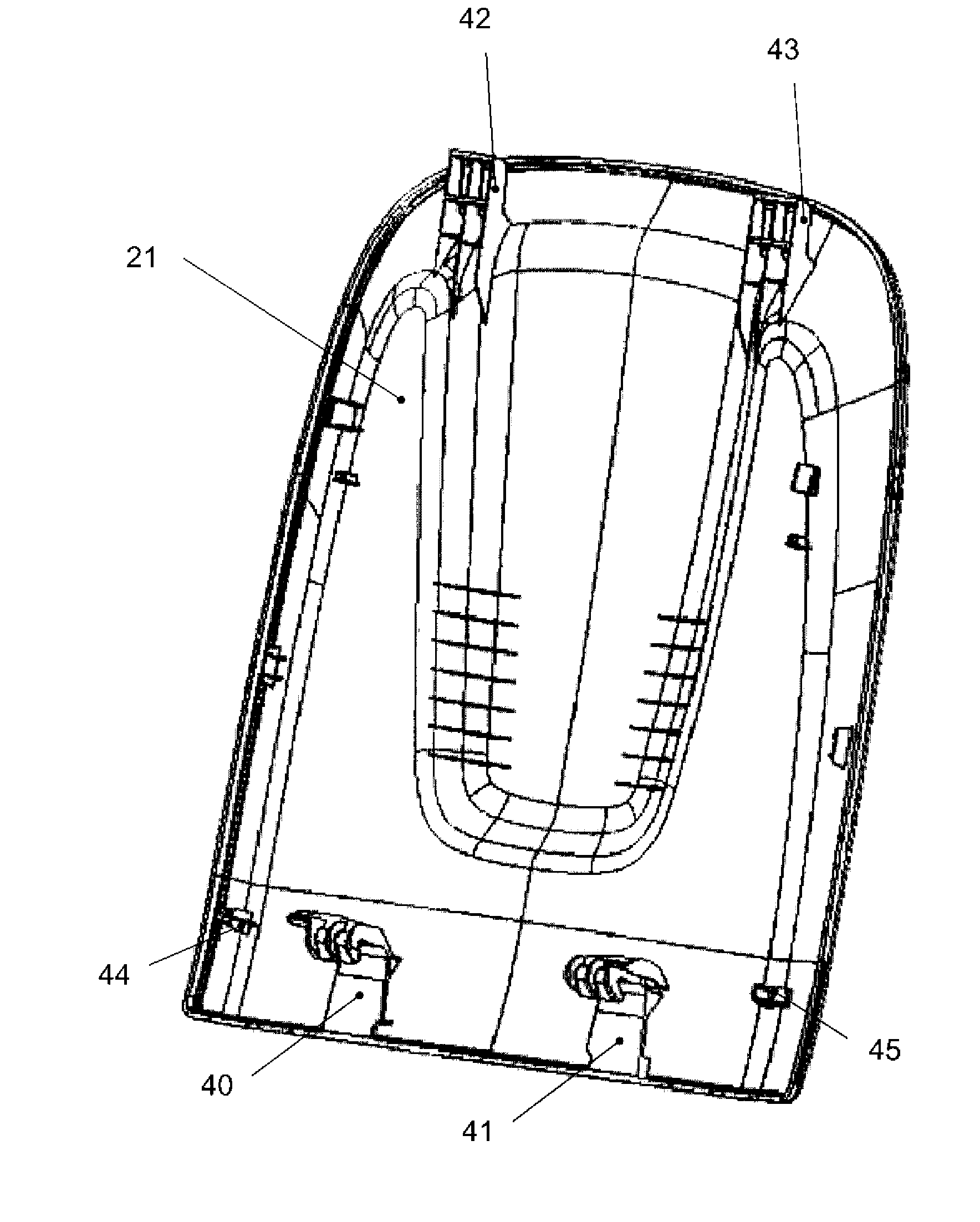
[0037]FIG. 3 shows the central part 21 from a side which, in the fitted state, faces the anti-whiplash vehicle seat 1. The cen...


PUM

PropertyMeasurementUnit
distanceaaaaaaaaaa
distanceaaaaaaaaaa
angleaaaaaaaaaa

Abstract

The invention relates to an anti-whiplash vehicle seat for a motor vehicle, with a rear backrest covering, wherein the rear backrest covering includes a fixed side part and a central part, wherein the central part is mechanically fastened to the vehicle seat by a resilient element, and wherein the resilient element is fastened to the vehicle seat by a hook.

Description

FIELD OF THE INVENTION[0001]The invention relates to a vehicle seat, in particular for a motor vehicle, with a rear backrest covering, wherein the rear backrest covering comprises a fixed side part and a central part, and wherein the central part is mechanically fastened, in particular at least in its lower region, to the vehicle seat by means of a resilient element. The vehicle seat is to be suitable for reducing or avoiding whiplash, in particular in the event of an impact from the rear.BACKGROUND INFORMATION[0002]In a passive anti-whiplash system, seat components, even the rear panelling parts, contribute to carrying out the anti-whiplash function. In the event of an impact from the rear, the rear wall of the seat component is subjected to a severe loading by the occupant plunging a small distance into it. However, an increased plunging-in distance is desirable if an occupant's head is to whip as little as possible to the rear. A simultaneous and uniform interception of an occupa...

Claims


Application Information

Patent Timeline
Patent Type & Authority Applications(United States)
IPC IPC(8): A47C7/02
CPCB60N2/4214Y10T29/49826B60N2/42709B60N2/6009
Inventor KRAFT, DIETER
Owner FAURECIA AUTOSITZE
Learn More