Compact robust linear position sensor

a position sensor, robust technology, applied in the direction of electric/magnetic position measurement, continuously variable inductance/transformer, instruments, etc., can solve the problems of optical types of sensors, bulk and cost of magnetic circuits including bias magnets, and the cost of either the hall or the mr devi

Inactive Publication Date: 2008-11-20
DELPHI TECH INC
View PDF16 Cites 34 Cited by
  • Summary
  • Abstract
  • Description
  • Claims
  • Application Information

AI Technical Summary

Problems solved by technology

In addition, a minimum level of durability is required, which virtually precludes optical types of sensors, and to a large degree, capacitive sensors.
The disadvantages are th

Method used


Image

  • Compact robust linear position sensor
  • Compact robust linear position sensor
  • Compact robust linear position sensor

Examples


Embodiment Construction

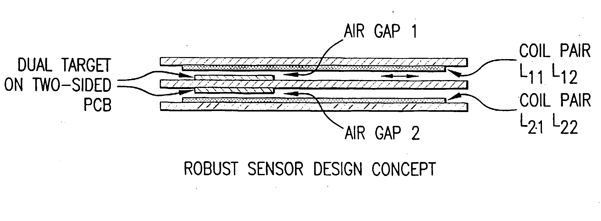
[0014]Applicants teach a simple, robust and very inexpensive linear ratiometric position sensor. It is an inductive sensor comprising a pair of stationary planar air-core coils formed on a printed circuit board (PCB) and a moving target consisting of a thin sheet of copper also formed on a PCB. It provides several improvements over the known art.[0015]decreased sensor length;[0016]simplicity in designing desired output characteristics; and[0017]insensitivity to air gap variations.

Decreased Sensor Length

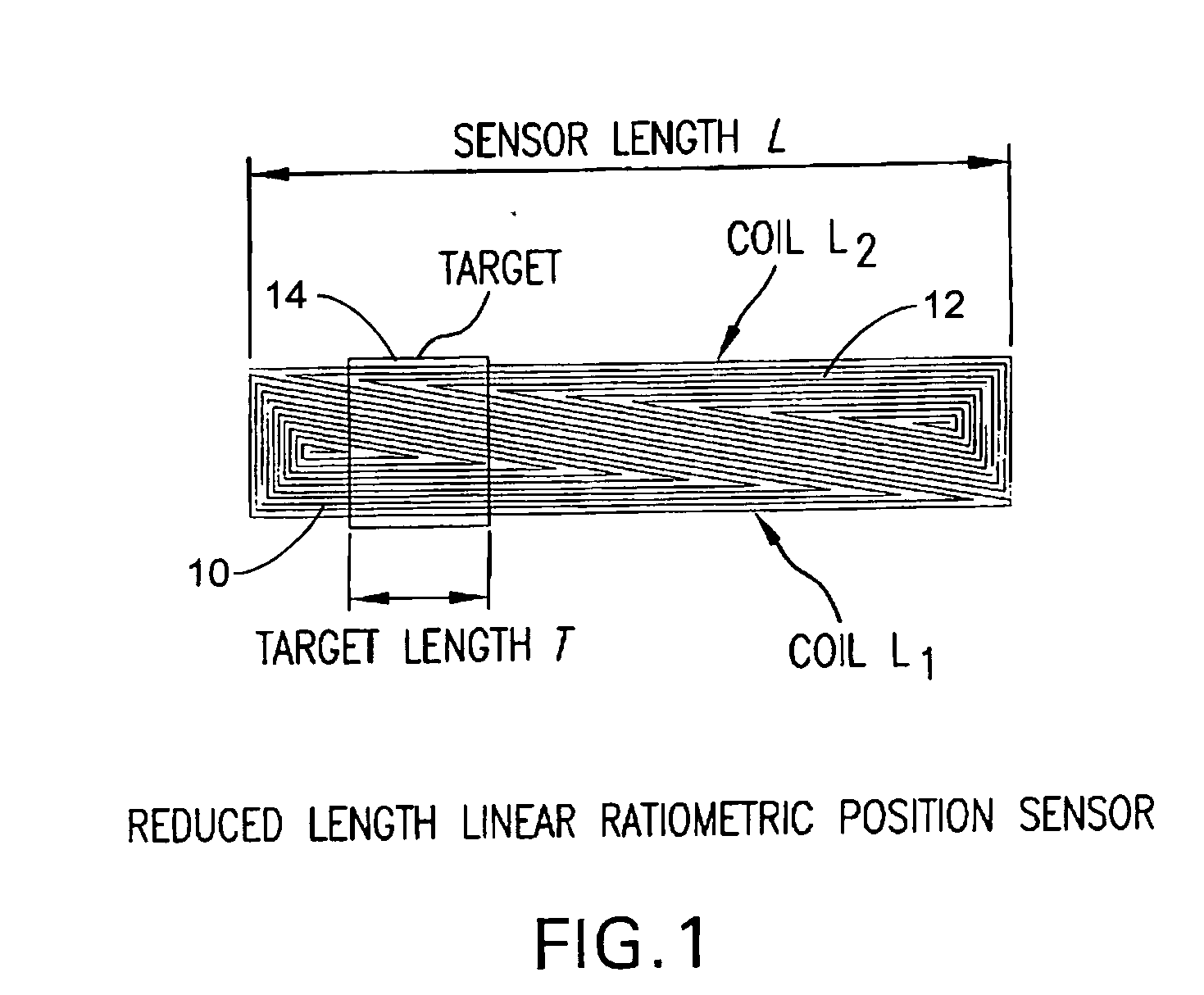
[0018]The present sensor offers design freedom to reduce its length without affecting its sensing range. It is accomplished by the use of a pair of planar triangular coils 10, 12 located side-by-side and a short target14 as shown in FIG. 1.

[0019]The sensing range of the sensor is:

X=L−T where 0

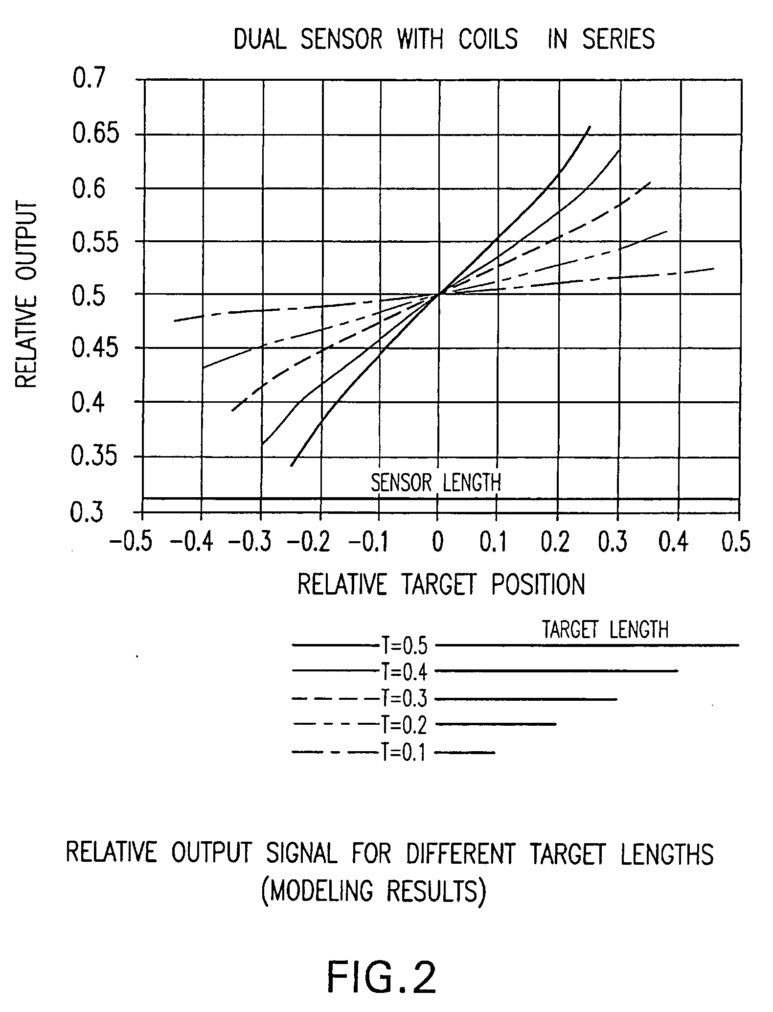
[0020]There is, however, some limitation for using a short target. The shorter the target relative to the sensor length, the lower the output signal, as illustrated in FIG. 2. Neverth...


PUM


Abstract

The present invention is directed to a position sensor, comprising a printed circuit board; a pair of stationary planar air-core coils formed in a trapezoidal or rectangular shape and side-by-side one another on the printed circuit board, coil windings being relatively uniformly distributed over a predetermined area of the printed circuit board; and a moving target formed by a sheet of copper on the printed circuit board.

Description

TECHNICAL FIELD[0001]The present invention relates to a compact robust linear position sensor.BACKGROUND[0002]A variety of automotive and industrial control system require absolute position sensors, either linear or angular, desirably, non-contacting and capable of operating down to a zero speed. In addition, a minimum level of durability is required, which virtually precludes optical types of sensors, and to a large degree, capacitive sensors.[0003]The most frequently used type of sensor satisfying the above requirements is a magnetic sensor comprising an analog Hall or an anisotropic magnetoresistor (MR) device, and a position responsive magnetic circuit, which varies the magnetic flux as a function of position. The disadvantages are the bulk and cost of the magnetic circuit including the bias magnet, and the cost of either the Hall or the MR device, which must include a complex signal processing capability.SUMMARY OF THE INVENTION[0004]The present invention relates to a position ...

Claims


Application Information

Patent Timeline
IPC IPC(8): H01F5/02G01B7/14
CPCG01B7/003G01D5/2053H01F21/10H01F27/2804
Inventor SCHROEDER, THADDEUSOMEKANDA, AVOKI
Owner DELPHI TECH INC
Why Eureka
Try Eureka