

Image-pickup apparatus
- Summary
- Abstract
- Description
- Claims
- Application Information
AI Technical Summary
Benefits of technology
Problems solved by technology
Method used
Image

Examples
first embodiment
1. First Embodiment
1-1. Apparatus Overview
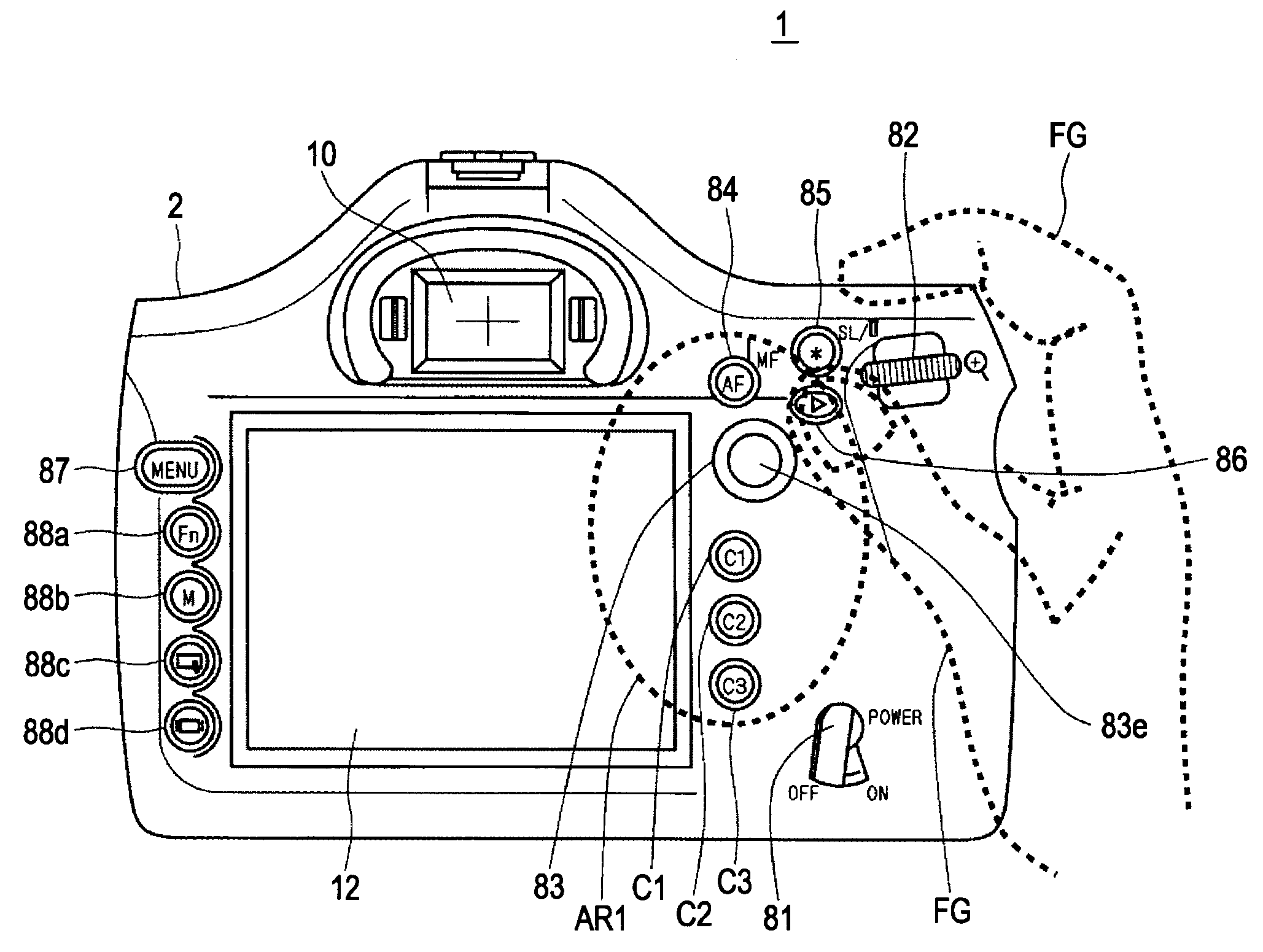
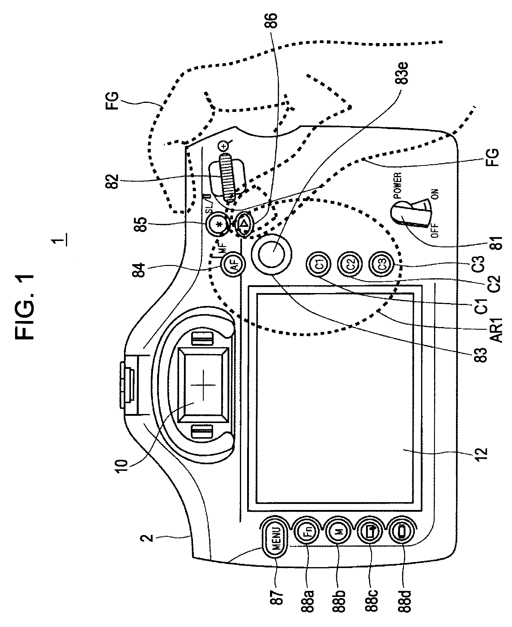
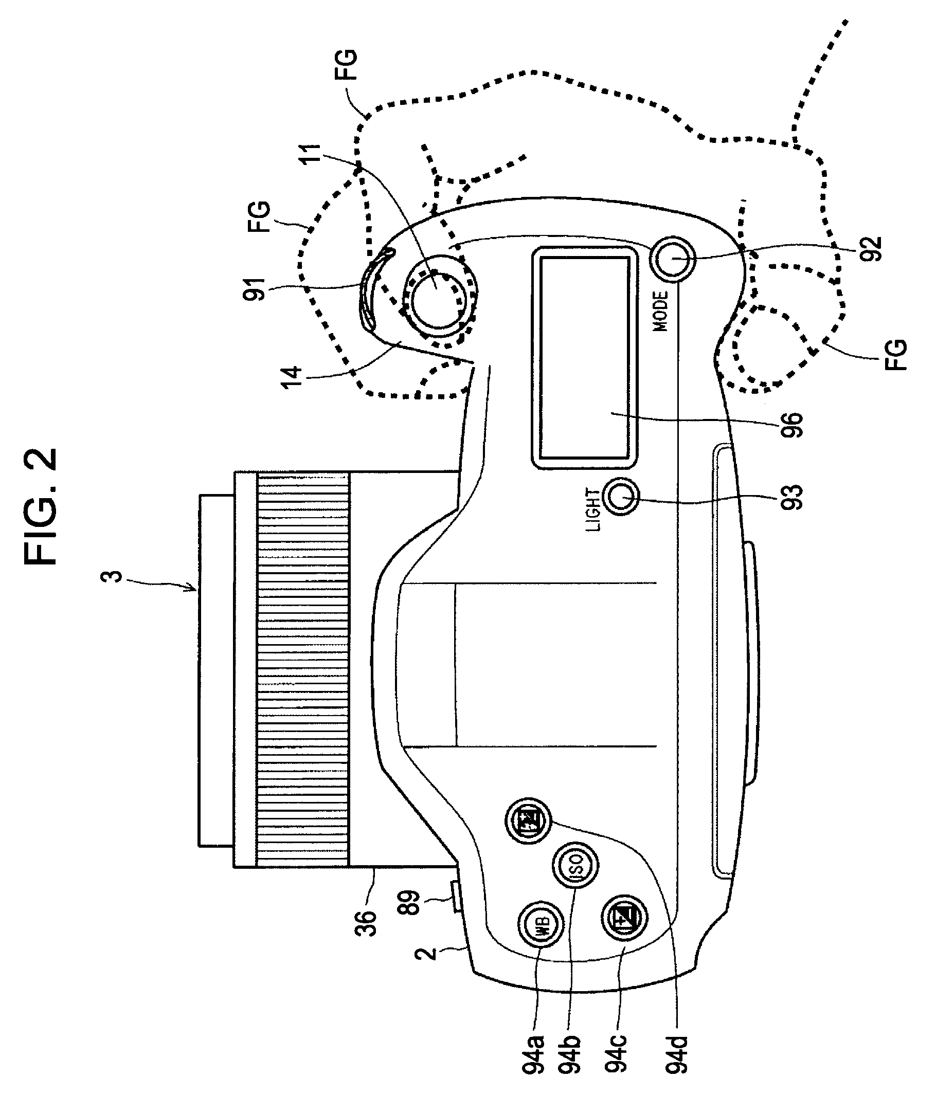
[0035]FIGS. 1 and 2 are outside drawings of an image-pickup apparatus 1 according to a first embodiment; FIG. 1 is an outer rear view of the image-pickup apparatus 1; and FIG. 2 is an outer top view of the image-pickup apparatus 1. The image-pickup apparatus 1 is a single-lens reflex digital camera with an interchangeable lens.
[0036]As shown in FIG. 2, etc., the image-pickup apparatus 1 includes a camera body 2 having an interchangeable taking-lens unit 3 detachably mounted thereon.
[0037]The taking-lens unit 3 mainly includes a lens barrel 36, a lens group 37 (see FIG. 3) accommodated within the lens barrel 36, and a diaphragm. The lens group 37 includes a focusing lens changing the focal position by its movement in the optical axial direction.
[0038]The camera body 2 is provided with an annular mount part Mt (not shown) arranged roughly at the front center to be mounted by the taking-lens unit 3 and a release button 89 arranged in the vicini...
PUM
 Abstract
Description
Claims
Application Information