Keyboard connection configuration and electronic device

a technology of electronic devices and keyboards, applied in the direction of instruments, portable computers, electric apparatus casings/cabinets/drawers, etc., can solve the problems of difficulty in maintenance, deterioration of operation sense when pressing an operating key, etc., to improve ease of maintenance, excellent operation feeling, and disassembly of the keyboard from the casing

Inactive Publication Date: 2008-11-20
SONY CORP
View PDF3 Cites 12 Cited by
  • Summary
  • Abstract
  • Description
  • Claims
  • Application Information

AI Technical Summary

Benefits of technology

[0015]Therefore, a strong connection state of the keyboard as to the casing can be provided. Further, excellent operation feeling can be provided when pressing an operating key without causing the keyboard to float up from the casing.
[0016]A plurality of through holes, which continue to extend the plurality of connection retaining portions, may be formed in the casing. Each of the plurality of retaining portions is inserted in a through hole and in a state in which the plurality of retaining portions are inserted in the plurality of through holes in the layering direction of the keyboard and the casing respectively, the keyboard is configured to slide relative to the casing. Thus, the plurality of retaining portions are retained in the plurality of connection retaining portions respectively to connect the keyboard to the casing. Accordingly there is no need to connect the keyboard to the casing with a screw-thread using a screw clamp, disassembly of the keyboard from the casing can be readily performed, and ease of maintenance can be improved.
[0017]Another aspect of the invention provides a keyboard cover fixed to the placement base from the opposite side of the casing, whereby rigidity of the keyboard and device main frame portion can be enhanced.

Problems solved by technology

Thus, if the backing plate is bent due to aging, temperature environment, or the like, the center of the keyboard floats upwards from the casing, and the sense of operation when pressing an operating key deteriorates, in some cases.
In order to prevent bending of the backing plate, for example, there is a method for fixing the center portion of the keyboard to the casing using screw-thread members, but this arrangement can create difficulties upon disassembly of the keyboard from the casing, and thus can lead to difficulty in maintenance.

Method used


Image

  • Keyboard connection configuration and electronic device
  • Keyboard connection configuration and electronic device
  • Keyboard connection configuration and electronic device

Examples


Embodiment Construction

[0056]Preferred embodiments for implementing the present invention will be described below with reference to the appended drawings. With the non-limiting embodiments described below, an electronic device according to the present invention is applied to a personal computer serving as an infonnation processing device.

[0057]With the following description, in a state in which a user visually recognizes the display screen of the personal computer, the front-and-rear, vertical, and horizontal directions are shown as viewed from the user. Accordingly, the user side is assumed to be the front. Note that the front-and-rear, vertical, and horizontal directions shown below are for the sake of convenience of description, and implementation of the present invention is not restricted to those directions.

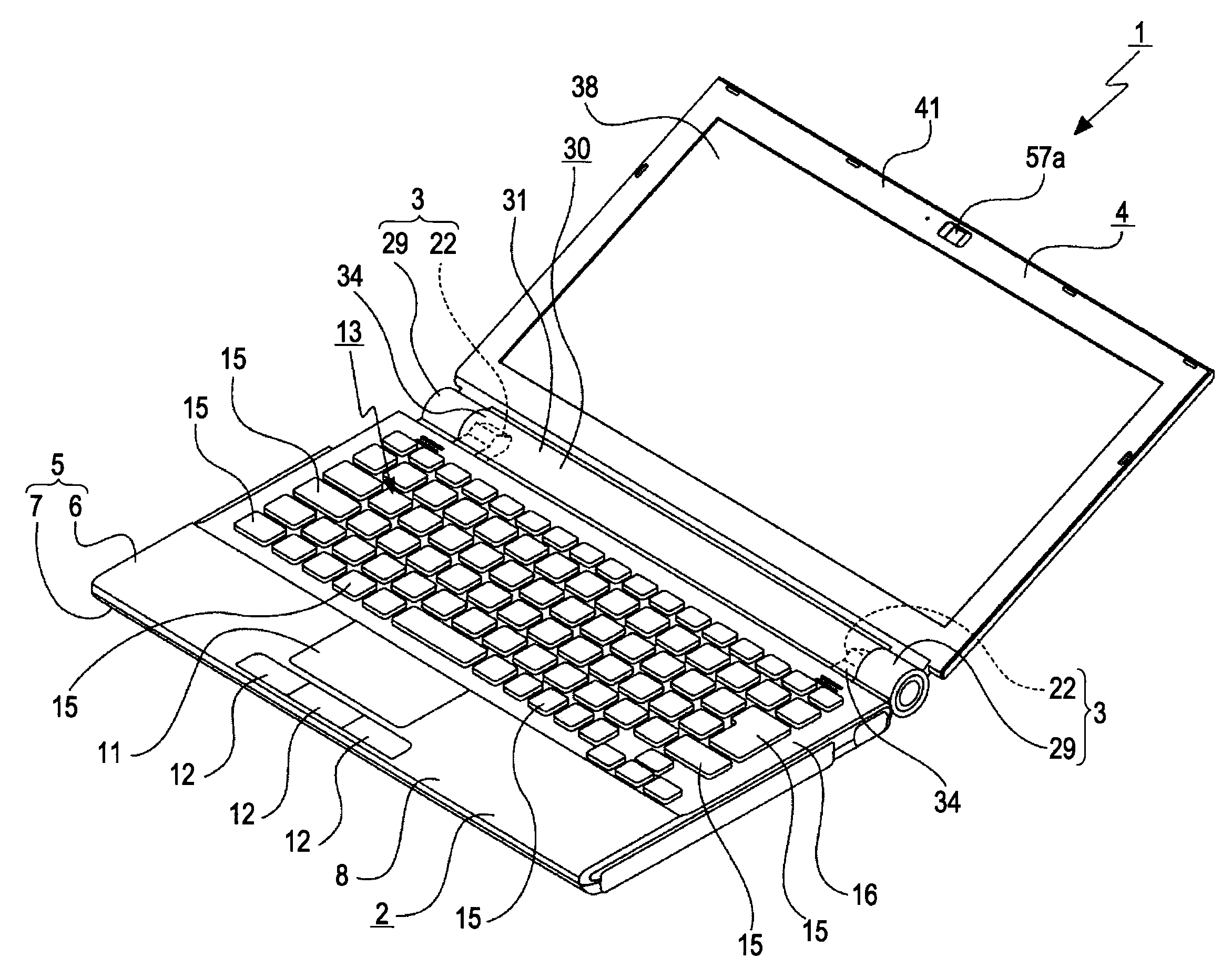
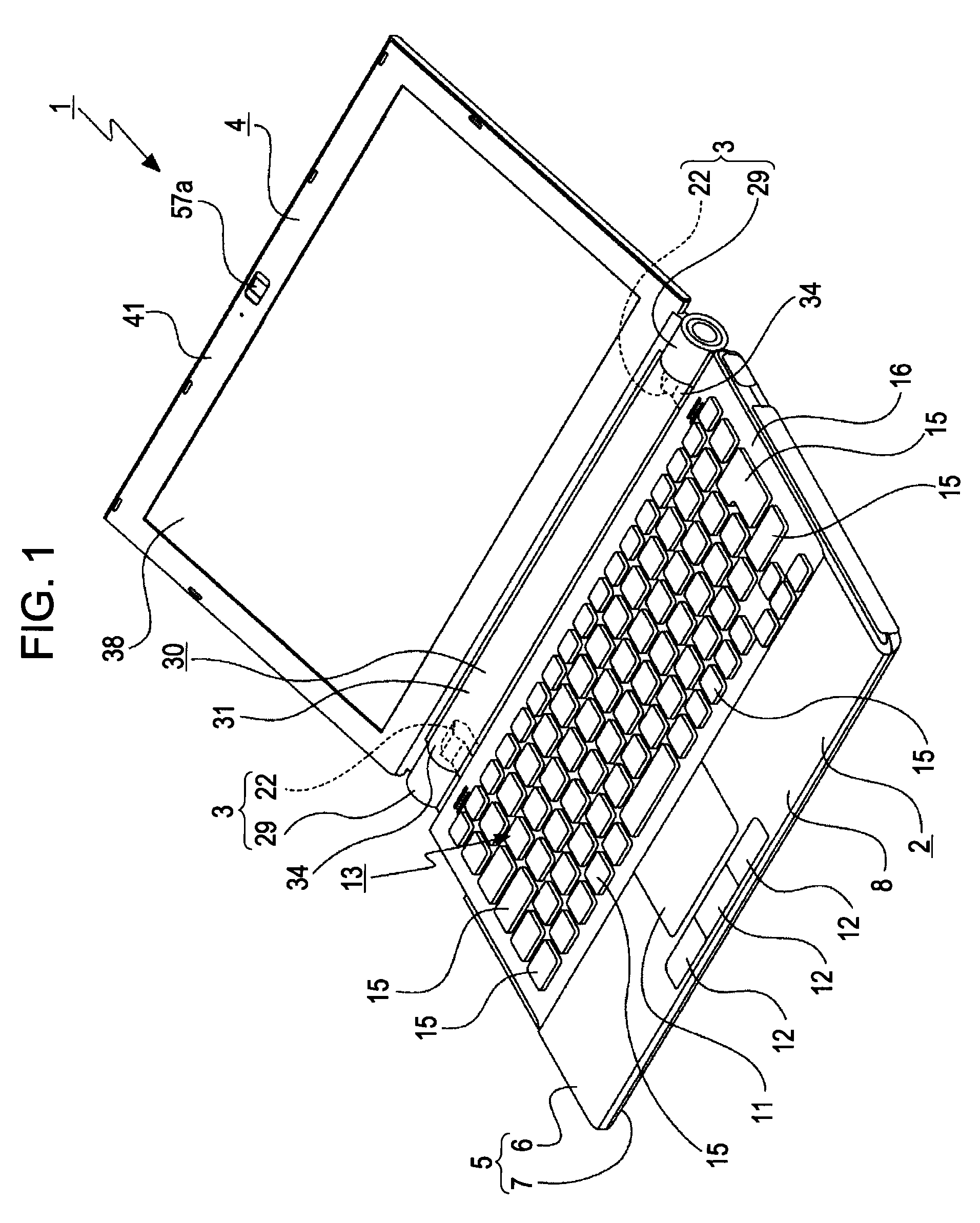
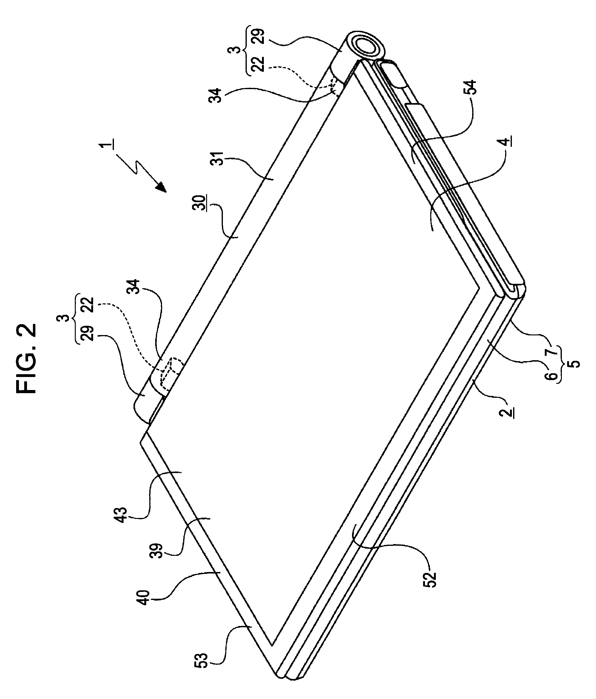
[0058]An electronic device, in this example, a personal computer 1 includes a display portion 4 supported with the rear edge portion of a device main frame portion 2 via hinge portions 3 so as to ...


PUM


Abstract

An electronic device includes a device main frame portion, a display portion supported by the device main frame portion, a keyboard, and a casing on which the keyboard is disposed. The keyboard includes a plurality of operating keys, a placement base in which the plurality of operating keys are disposed, and a plurality of retaining portions disposed on at least portions of the placement base of the keyboard other than an outer circumferential portion. The keyboard is disposed on a casing. A plurality of connection retaining portions are provided on the casing, on which connection retaining portions the plurality of retaining portions of the placement base are retained, respectively.

Description

CROSS REFERENCES TO RELATED APPLICATIONS[0001]The present invention contains subject matter related to and claims priority to Japanese Patent Application JP 2007-130721, filed in the Japanese Patent Office on May 16, 2007, the entire contents of which Japanese Patent Application are incorporated herein by reference.BACKGROUND OF THE INVENTION[0002]1. Field of the Invention[0003]The present invention relates to keyboard connection configurations and electronic devices. One example of the present invention relates to ensuring a strong connection of a keyboard to a casing by providing multiple retaining portions at predetermined positions on the keyboard.[0004]2. Description of the Related Art[0005]In electronic devices such as personal computers, cellular phones, and PDAs (Personal Digital Assistant), etc., there is typically a keyboard (keyboard unit) having multiple operating keys. The keyboard is typically connected to a casing (see Japanese Patent No. 3218819).[0006]With the elect...

Claims


Application Information

Patent Timeline
Patent Type & Authority Applications(United States)
IPC IPC(8): H05K5/02
CPCG06F1/1616G06F1/1635G06F1/1637G06F1/166G06F1/1662G06F1/1681G06F1/1698
Inventor KOBAYASHI, NORIOHANAMURA, HIDEKI
Owner SONY CORP
Why Eureka
Try Eureka